Introduction
The second version of our wireless extender test process changes the test location and changes the test client and reference router. The latter change is being made to test newer designs using 802.11ac technology. The change in test location is to ensure that the tests are free of effects from surrounding wireless activity.
Hardware Used
Testing uses an ASUS RT-AC66U router with firmware 3.0.0.4.374_726-g10636ee. This router enables testing of up to AC1600 class extenders. It was chosen because it is also used as the reference router for our wireless adapter and bridge test process.
The test client is a NETGEAR A6200 AC1200 USB adapter with 6.30.145.30 Windows driver in an Intel i3 or higher class Windows 7 notebook. It was chosen because we are familiar with it and have used it for other projects.
Setup
The test process requires a true "dead zone" for both 2.4 and 5 GHz bands, which was not possible to achieve by using the router’s transmit power adjustment (it had no effect) or by adding fixed attenuators between the router and antennas. So we had to resort to removing the router antennas and placing it inside one of our octoScope octoBox anechoic RF chambers. The router was positioned as shown in the photo below, with the antenna connectors facing the rear of the box.
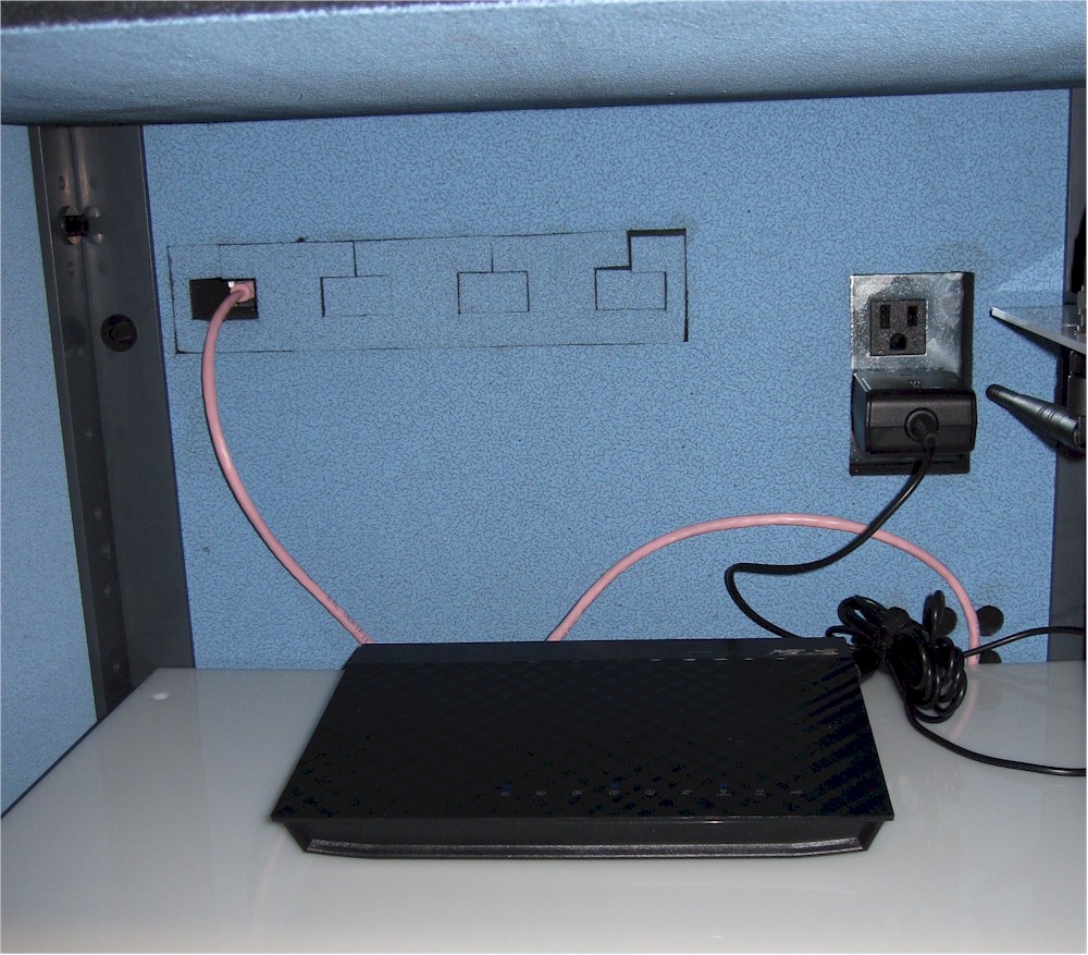
Placement of ASUS RT-AC66U reference router in octoBox
To further reduce the router’s signal, the chamber door was closed most of the way as shown below.
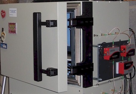
octoBox door position
The test area is on the lower level of a 3300 square foot two-level home built on a hillside lot with 2×6 wood-frame exterior walls, 2×4 wood-frame sheetrock interior walls, and metal and metalized plastic ducting for the heating and air conditioning system. The reference router is located in a storage room at one end of the home and the test client laptop is located in a bathroom at the opposite end of the home.
The Extender Under Test is physically located midway between the test laptop and base router, with approximately 20 feet between the extender and each other device.
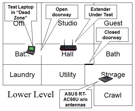
Floor Plan
Both rooms open onto a long hallway with doors located as shown in the floorplan. The door to the bathroom is open and the door to the storage area is closed.
The "dead zone" was verified two ways. First, we attempted to associate the A6200 test client with the RT-AC66U on both 2.4 and 5 GHz. In both cases, we were able to connect, but the connection link rate was below 5 Mbps and would not support successful ping or IxChariot test start. We also experienced frequent disconnects.
The second method was to use inSSIDer to measure signal level. The screenshot below shows an intermittent connection to the RT-AC66U in 2.4 GHz (lower trace in the upper right hand box).
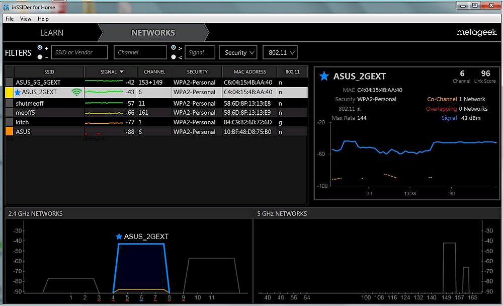
inSSIDer plot of 2.4 GHz signal difference
The 5 GHz plot shows a similar story, with frequent breaks in the signal (lower trace).
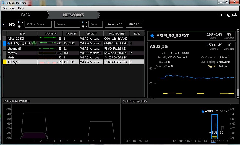
inSSIDer plot of 5 GHz signal difference
Test Procedure
Note: "Downlink" means data flows from router to Extender to client device. "Uplink" means data flows from client device to Extender to router.
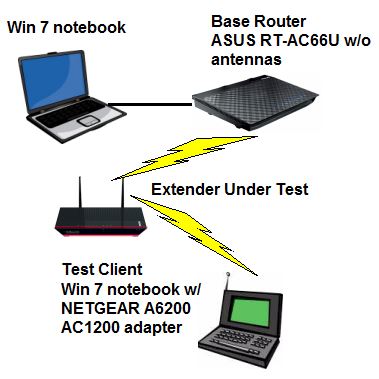
The test configuration is shown in the diagram below. The 2.4 GHz radio in the RT-AC66U is set to channel 6 using 20 MHz bandwidth mode. The 5 GHz radio is set to channel 153 and Auto 20/40/80 MHz bandwidth mode. No other wireless activity is present during testing.
The extender under test is first connected to the base router using a WPA2/AES secured connection. For dual-band extenders, only one band is connected at a time.
Wireless Extender Test Setup
Two sets of tests are run. One measures wireless "extended" throughput between the ASUS router and test client, connected through the extender under test. The other measures wired "extender" throughput from base router to the extender under test by disabling the client laptop’s wireless and connecting the laptop to the extender’s Ethernet port.
For each test the IxChariot Throughput.scr script is run for 1 minute in real-time mode using TCP/IP in both uplink (client to AP) and downlink (AP to client) directions. The only modification made to the IxChariot script is to change the file size from its default of 100,000 Bytes to 1 – 5,000,000 Bytes depending on the speed of the connection. Test results are then entered into the database and are available in the Wireless Extender Charts

