Introduction

Wireless networks are a wonderful thing. However, the freedom and convenience they provide can also come with a healthy dose of frustration and annoyance. Your pain might come in the form of frequent network disconnects, sluggish speed, inability to connect or, if you’re really lucky, combinations of all three.
Fortunately, armed with a basic understanding of how wireless networks (also commonly known as wireless LANs or WLANs) work and some simple troubleshooting techniques, you can find, fix or at least minimize many WLAN problems.
In this first article of a series, I’ll first provide an explanation of WLAN basics and then move on to describe common wireless problem symptoms and their probable causes. The goal is to help you choose the correct path toward solving the problem you actually have. This is important, since some "fixes" that are applied blindly can often make the actual problem worse!
WLAN Types
The two main types of wireless networks are Infrastructure, which are the most
commonly encountered, and ad hoc.
In Infrastructure wireless networks, wireless clients (commonly referred to as Stations or STAs) connect to access points (APs), which coordinate and relay traffic among STAs. Note that in an Infrastructure WLAN, STAs do not directly communicate, which is a common misconception. APs also bridge data traffic between the wireless and wired segments of a LAN.
Note: A wireless router contains an access point (AP), router and switch combined to share a single Internet connection among wired and wireless clients. Wireless routers are normally used in small networks at homes and small businesses that require only a single AP. However, if additional wireless coverage is required, additional APs can be connected to the wireless router.
In this series, I’ll usually use the term AP, but this can also mean wireless router.
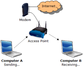
Figure 1 illustrates the coordination and relaying functions in an Infrastructure WLAN. For a file transfer from Computer A to B, the data packets are transmitted from Computer A to the AP, then retransmitted to Computer B.

Figure 1: Sending and receiving on an infrastructure wireless network
In ad hoc wireless networks, STAs create a peer-to-peer network without an access point. The communication on a ad hoc network is regulated by protocols that are included in the 802.11 standards and implemented in each STA.
In this series, we’ll concentrate on Infrastructure wireless networks since they are the predominant type.
Channels
As you may have noticed when configuring your AP, there are 11 channels available in the U.S. for operation in the 2.4 GHz band. (The 2.4 GHz band is used by 802.11b, 802.11g and draft 802.11n gear.)
Figure 2 provides a visual representation of the channels and frequencies.

Figure 2: Depiction of 2.4GHz frequencies for 802.11b/g channels.
From
Wi-Fi Hotspots: Setting Up Public Wireless Internet Access
(Cisco Press, 2006) by
Eric Geier , used by permission
While technically you can choose any of these channels, in practice, you should use only channels 1, 6, or 11. The reason for this limitation is channel overlap. 802.11b and g use eleven channels in the 2.4GHz band, spaced at 5MHz intervals. Since the commonly accepted width of each channel is 22MHz for 802.11b and 20MHz for 802.11g, both 802.11b and g are said to have three non-overlapping channels (1, 6 and 11).
Tip: Now-defunct wireless networking management company Cirond argued that there are actually four channels (1, 4, 8, 11) that can be used for 802.11b and g with virtually no performance penalty.
Now if all the energy of the transmitted signal actually were contained within a 20 (or 22MHz) band, the definition of “non-overlapping” might be simpler. But reality is somewhat more complicated.

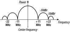
Figure 3: 802.11b Transmit Spectrum Mask
From Matthew Gast’s 802.11 Wireless Networks: The Definitive Guide , used by permission
Figure 3 shows an idealized spectral plot (power vs frequency) of an 802.11b signal. To paraphrase the explanation in Chapter 10 of Matthew Gast’s excellent book, this plot shows that transmitted power is reduced by 30dB (1/1,000) below the power at the center of the channel (that’s what the dBr notation means) at +/-11MHz away from the channel center and 50dB (1/100,000) below at +/-22MHz away.
NOTE: The following spectrum diagrams are based on Figure 3 and are not done to exact scale. Any inaccuracies are not intentional!
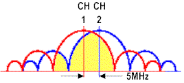
Since 11b and g channels are on 5MHz spacings, two channels right next to each other (1 and 2 for example) would overlap as shown in Figure 4.

Figure 4: 802.11b adjacent channel overlap
The yellow shaded area represents the power from channel 2’s signal that overlaps into channel 1’s main lobe (the largest “hump” and also the frequency band that contains most of the signal’s power). Since a significant amount of channel 2’s main lobe overlaps into channel 1’s main lobe (and vice versa), communication on both channels will suffer. Contrast this picture with the situation shown in Figure 5.

Figure 5: 802.11b “non-overlapping” channel overlap
This figure has the same scale as Figure 4, but shows signals in the “non-overlapping” channels 1, 6 and 11. Since the power from each signal doesn’t magically stop at the 22MHz channel boundaries, there is still overlap between “non-overlapping” channels. But in this case, the yellow shaded area that represents channel 11’s power that is overlapping into the main lobe of channel 6 is at least 30 dB lower (1/1000) than channel 11’s peak power.
Put simply, channels 1, 6 and 11 are considered to be “non-overlapping” because the amount of power that does overlap is supposedly too small to significantly affect each channel’s operation. Whether that’s actually the case, however, depends on many other factors, including the device’s Adjacent Channel Rejection (ACR) capability, and, of course, the physical distance between devices on different channels. By the way, although I’ve been using examples based on 802.11b, the situation is pretty much the same for 802.11g.
Note: For a better picture of what real 802.11g signals look like when captured on a spectrum analyzer you can refer to some screen shots shown here.
RF Basics
When troubleshooting your wireless network, it is helpful to understand how wireless signals, or RF (Radio Frequencies), travel through your home or office. Similar to other radio devices such as cordless phones or walkie-talkies, signal quality and strength decreases as the distance between the transmitter and receiver (wireless router and computer) increases. Additionally, obstacles such as walls, floors, and furniture can block or reduce the wireless signal.
To better understand how these signals travel, imagine your
AP as a tiny light—a naked light bulb (to simulate an omni-directional, or
dipole antenna). This analogy works well in an
"open field" environment where there is a clear line of sight
between the bulb (your Access Point or wireless Router) and your eye
(your wireless-equipped laptop), but requires a little bit of tweaking for an indoor environment.
So also picture your home’s walls, ceilings,
and furniture not as solid objects, but more like translucent panels or
objects with
varying opacity. The more panels or objects between the bulb and your eye, the more difficult it will be to see the light.
The antennas used on your wireless networking devices play a major role in how the signal propagates, or travels. Most wireless networking gear (wireless routers and adapters) come with omni-directional antennas, which means the signal is transmitted with equal strength in all directions. Other types of antennas include directional antennas with varying "gains" or amplification factors and high-gain omni-directional antennas.
Going back to the light bulb example, you could think of putting a
curved reflector behind the naked light bulb as similar to attaching a directional antenna to your AP. The reflector wouldn’t change the amount of light (radio
power from the AP) being transmitted, but instead concentrate the light in a desired direction.
We will cover more on antennas and their uses later in this series.
RF Interference
In addition to interference caused by other wireless networks on the same channel or from overlapping channels, other radio devices can interfere with wireless networks. The following devices that use (or bleed onto) the 2.4 GHz frequency band are common culprits:
- Cordless phones
- Baby monitors
- Kitchen microwaves
- Wireless speakers and headphones
- Bluetooth devices
Note: We are focusing primarily on the 2.4GHz band, which is used by 802.11b, g and draft n products. But similar interference problems can occur with 802.11a and draft 11n products that use the 5 GHz frequency band.
However, since each channel in the 5 GHz band uses non-overlapping frequencies, and 5 GHz WLAN gear is much less commonly used, interference is typically less of a problem. But it is only a matter of time until the 5 GHz band suffers from the same congestion as the 2.4 GHz band.
The effect of the interference by devices like these varies. It can be minimal, causing only a slight drop in performance and speed. However it is not uncommon for the interference to completely drown out the wireless signals, stopping your Wi-Fi network in its tracks.
An interesting round of tests performed by the Farpoint Group,
released in a paper last January titled The Effects of Interference on General WLAN Traffic, shows how bad interference can be to your
wireless network. They found that a microwave oven caused more than 62%
reduction of throughput (the amount of data transferred) on their wireless test
network compared to measurements without the intentional interference.
Additionally the study found a 89% reduction
from a neighboring wireless LAN and almost a 20% reduction in
throughput from a Bluetooth headset. But the most damaging interferer was a cordless phone, causing "complete obliteration (100% degradation) of a Wi-Fi link." (my cordless phone does this too!)
Revisiting the light bulb example, you could imagine these
interfering devices as "light" sources as well. Depending upon
the number, location, and power of these other light sources (2.4GHz
cordless phones or microwaves) it may make it difficult, or even impossible, to differentiate the light in the area from the lamp bulb (your AP) and the interfering sources.
We will cover more on how to address and overcome RF interference in another part of this series.
Problem Identification
Now that we’ve covered some Wi-Fi basics, it’s time to start figuring out the cause of your wireless LAN’s problems. This can be more difficult than you might expect, since wireless problem symptoms can often have multiple causes.
Table 1 presents the most common problem symptoms encountered and their possible causes. Note that some of the possible causes are common to multiple symptoms!
| Symptom | Possible Causes |
|---|---|
| WLAN doesn’t cover expected / required area | – Low signal – Too many obstacles – AP placement |
| Can’t connect to AP, even at close range | – STA configuration – AP configuration |
| Low and/or inconsistent throughput (actual operating speed) | – RF interference – Neighboring WLANs – Low signal |
| Computer intermittently connects with another network | – Neighboring WLANs – STA configuration – Low signal |
| AP intermittently disappears or disconnects | – RF interference – Neighboring WLANs – Low signal |
| Constantly changing link rate (i.e. "connection" speed reported by STA) | – RF interference – Neighboring WLANs – Low signal |
| Link rate never reaches advertised maximum | – STA configuration – AP configuration – Incompatible AP & STA |
Table 1: WLAN Problem Symptoms and Causes
Because of the multiple possible causes, getting to the cause of your problem may require multiple passes and careful experimentation. While you might be tempted to short-cut this process and just try to throw money at the problem by purchasing the latest wireless wonder being hyped by WLAN product manufacturers…don’t!
Although it’s possible that a new wireless thingy will solve your problem, keep in mind that the manufacturers are mainly focused on profits and market share. And the consumer WLAN industry has never been shy about introducing new technology that, at least in the early going, can cause as many problems as it solves.
Conclusion
To sum up the key points so far:
- Always use the non-overlapping 2.4 GHz channels: 1, 6, or 11.
- Think like radio waves (or light bulbs and lamps!) when troubleshooting your wireless network.
- Cordless phones, microwaves, and other 2.4 GHz devices can cause interference.
- Determine the underlying problem before trying to fix your network.
In Part 2, I’ll show you how to use equipment that you already have to perform a simple Site Survey.
