Introduction
The Diary of a New Home Network series proved to be very popular, as it seems as if I’m not the only one trying to save a buck by investing a little sweat equity into building a new home. In addition to the great feedback and ideas I received, a number of readers responded to our call and took the time to send in pictures and descriptions of their home networks.
We look at three systems, two of which use commercially-available structured wiring component systems. The other takes a decidedly non-commercial approach that may not be pretty to look at, but it gets the job done.
Network #1: Data, Phone, TV, And Whole-house Audio
Chris from Texas built his system using components from Leviton’s Integrated Networks product line. He was able to design and install the network while his home was being built, which was obviously a big help.
“My focus was to have distribution boxes for computer/phone/TV, with wiring that would control Leviton Decora Digital Chopin Volume Control modules,” Chris wrote. (Figure 1)
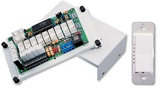
Figure 1: Decora Digital Chopin module
These are the Ethernet-controlled volume control modules that replace traditional transformers and rotary controls for whole-house audio distribution.
The heart of the system fits into two Leviton Structured Media Center Series 280 distribution boxes. Figure 2 shows the LAN / Network box with the cover on, and the other is for phone and TV / satellite and support for the Chopin modules.
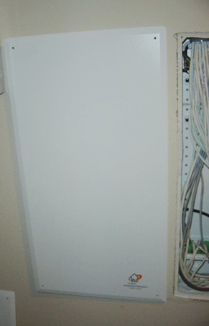
Figure 2: Leviton Structured Media Center Series 280 box
Chris paid about $69 for the boxes at his local Home Depot. He would have used a larger box, but Home Depot didn’t stock them.
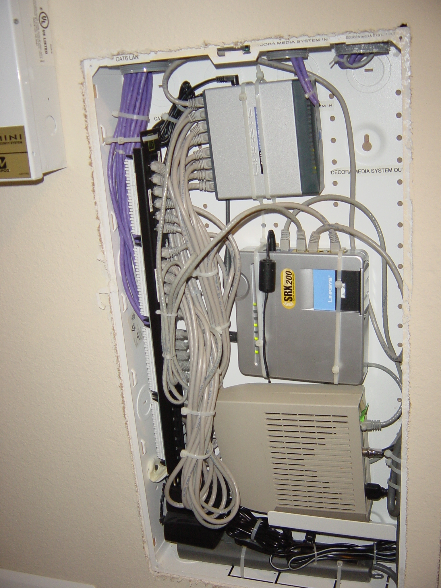
Figure 3: Open view of LAN box
(click image to enlarge)
Figure 3 shows the LAN box with cover off, where you can see the Leviton Cat 5e GigaMax Universal 24 port patch panel purchased on eBay for around $45 running along the left side of the box. The panel supports the approximately 17 Ethernet ports throughout Chris’ home.
“I could have used the smaller Leviton patch panels that fit wonderfully into these boxes…I think they come in groups of five”, Chris said. “However, the patch panel was cheaper and I was able to secure it to the side and free up space. It also was a gigabit [grade] patch panel, in case I upgraded in the future with my router and switch”.
The other components in the LAN cabinet are a Linksys SD216 16 port 10/100 switch (top), WRT54GX2 wireless router (center) and cable modem (bottom). If you look carefully, you can see the router’s two antennas, which are tucked underneath the cable bundles. Even with the cover on, Chris said that he gets a good enough wireless connection about 75 feet away.
AV Cabinet
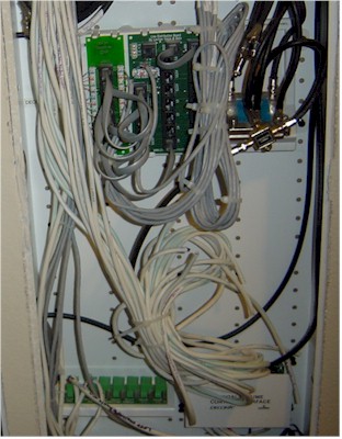
Figure 4 is a photo of both of the distribution boxes, which reveals the innards of the second (AV) cabinet. This box contains the phone TV, and audio distribution. The audio is still a work in progress. All that white wire is speaker cabling running to the Chopin box sitting in the lower right-hand corner of the cabinet.
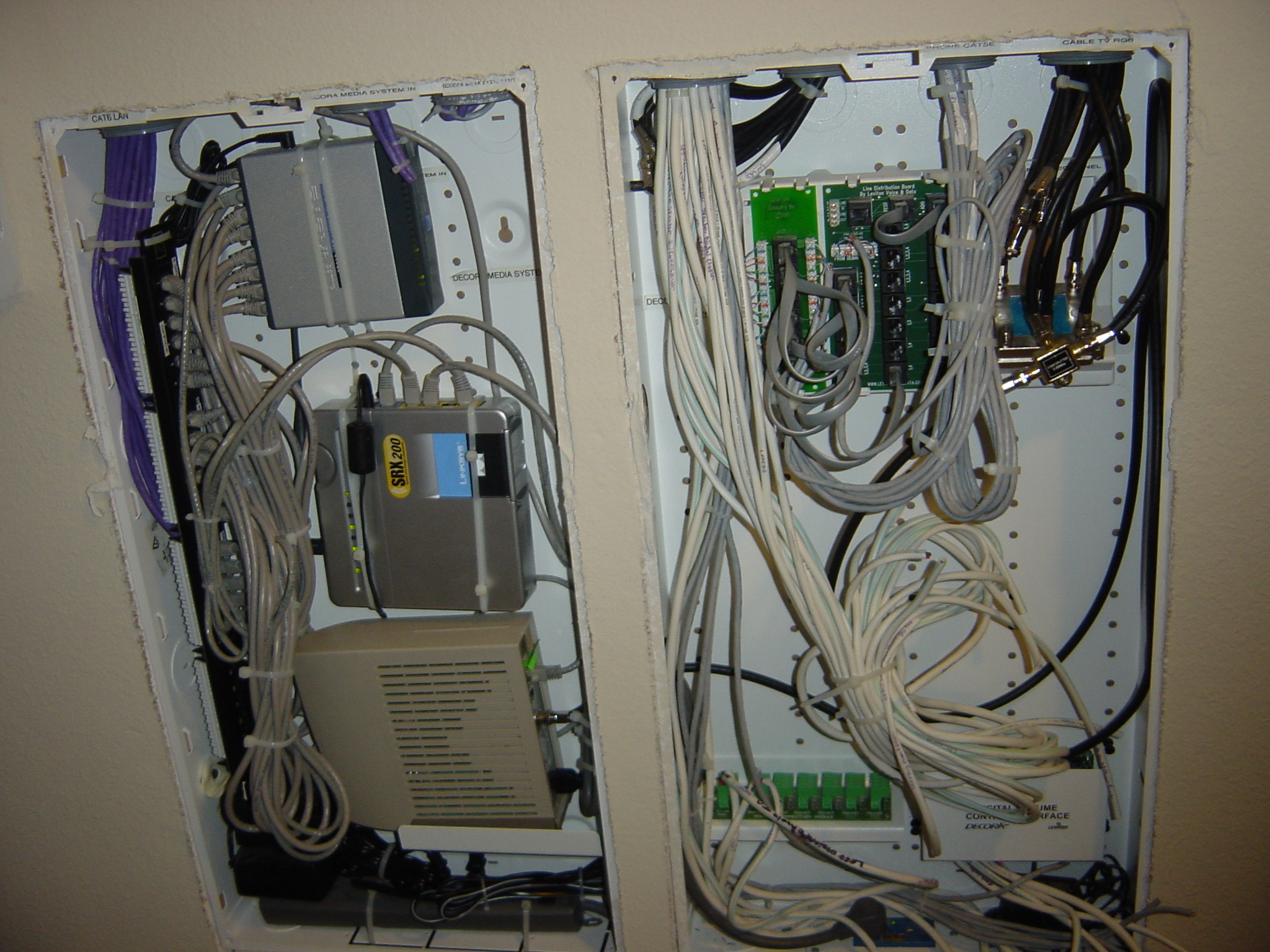
Figure 4: LAN and AV distribution boxes
(click image to enlarge)
Figure 5 shows the details of the phone and TV distribution, which is based around a Leviton Advanced Home Telephone and Video Panel. This panel combines a Leviton telephone line distribution module, category 5e voice and data board and a six-way 2 GHz video splitter. There are other models that have a whole-house DSL filter, but since Chris has cable-modem service, he opted for the model without it.
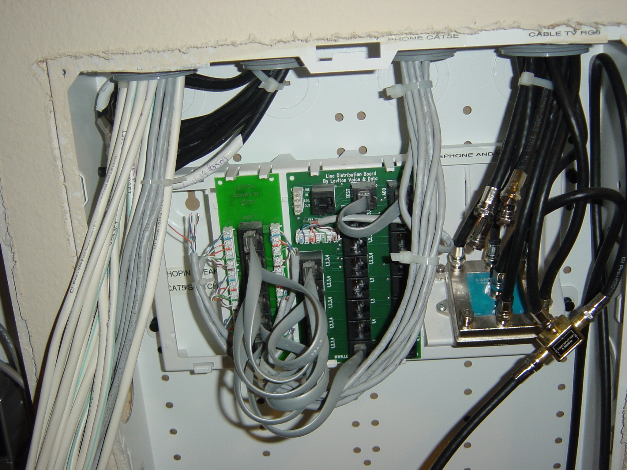
Figure 5: Detail of phone and TV distribution
(click image to enlarge)
The phone lines from the telco demarc box feed in from the left, terminate at the distribution module, then are fanned out to phone line drops via the voice and data board. The video splitter, as its name implies, fans out the video feed. You can get a little better idea of the phone interconnects from the close-up in Figure 6.

Figure 6: Close-up of phone distribution
(click image to enlarge)
Helpful Tips
Wrapping up the AV cabinet tour is a detail of the speaker distribution and control and power module sitting at the bottom of the cabinet. (Figure 7)

Figure 7: Speaker distribution and control
(click image to enlarge)
Again, there is all Leviton stuff here, including an AC power surge protective module, a speaker connection module and a Digital Chopin module.
To wrap things up, here are some tips that Chris found helpful in putting together his system:
- Running cable is really not that bad if you’ve got a lot of attic space and it’s during the building phase of your home; As for an existing home…well that’s another story. Either way, this is when you call in favor from a few friends. It took me three days or so to do all my wiring.
- I used CAT 6 instead of CAT 5 cable… it wasn’t that much more. No CAT 3…yuck. Think I paid $60 for a thousand feet off of eBay.
- RG6 cable quad shield was also purchased online for TV / satellite. The quality of the cable I got from eBay was better than at my local Home Depot store.
- I can’t say enough about Leviton products, from distribution boxes, phone distribution modules, CAT 5 patch panels, termination ends, wall plates…they have it all. Best of all, most of these can be found at Home Depot. But use eBay for the more expensive things. My phone module cost me $3from eBay.
- If you use a centralized distribution panel, make sure a licensed electrician runs power to it.
- Most importantly, write down your needs….map it out.
- Buy some punch down tools and some CAT 5/6 crimping tools and do the termination yourself. Don’t pay someone to do it, because it’s easy. Make sure you terminate both ends properly and follow the same TIA scheme.
Network #2: Data And Phone Only
Mike Rogers also handled his own new-home network installation. “I knew going into it, that networking the house was something I wanted done, but could not afford to pay someone to do,” he wrote. “Before the sheetrock was installed, I pulled two CAT 5e cables to every phone and cable outlet that the electricians had installed.”
The builder also allowed Rogers to choose the location of the phone and cable outlets. “I had them all located where I thought they would be best utilized,” he said. “This also made it easier than trying to fish wires out of the walls.”
Mike also took the opportunity to redo the phone wiring, which the electricians had daisy-chained from one jack to the next, instead of using “home run” wiring (when a separate cable for each jack runs back to a central location).
The installation has a total of seven phone and seven network connections run to every room in the house, including the kitchen. Some rooms have two drops where Mike wanted the cable and phone connections to be on different walls.
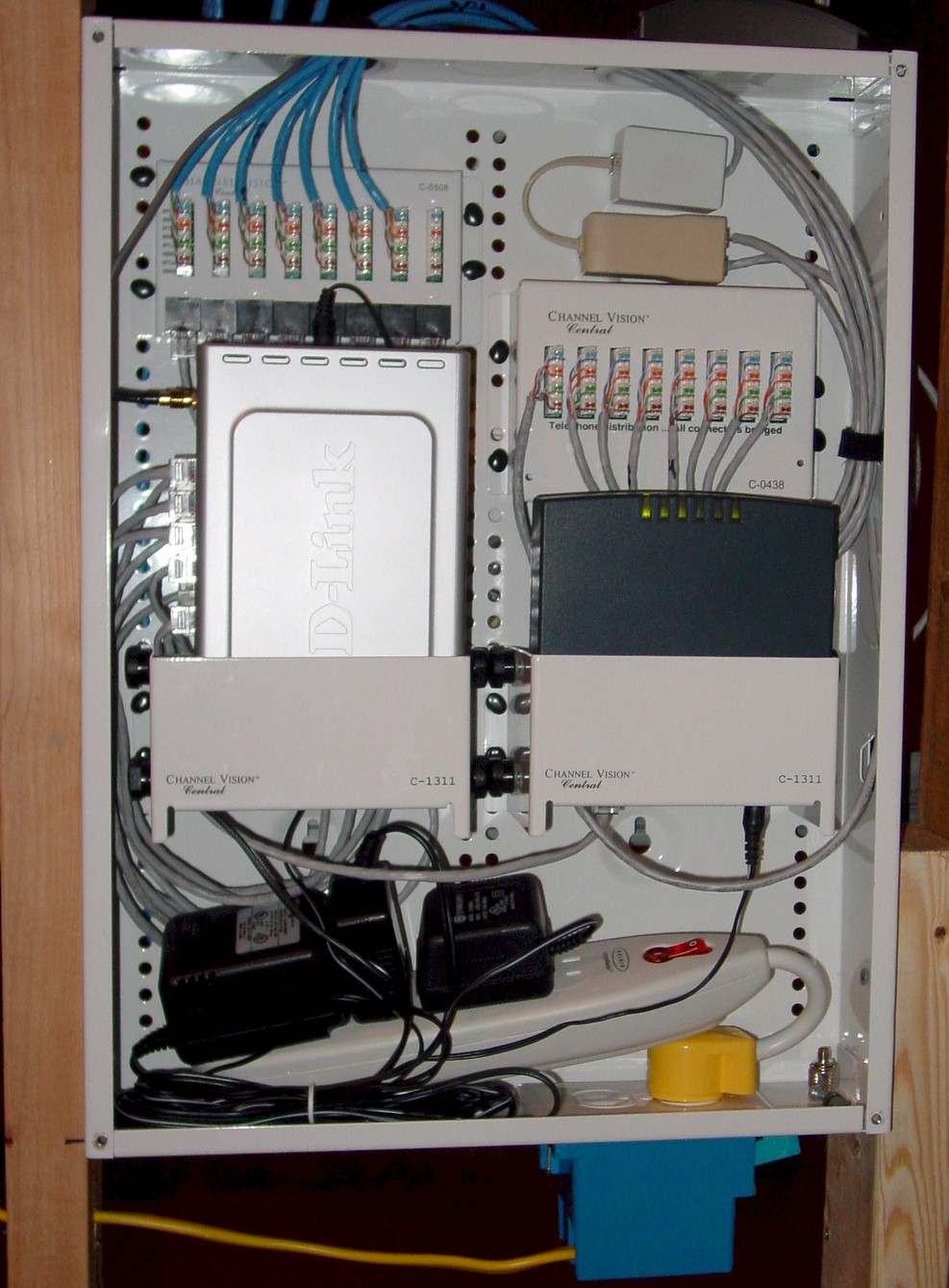
Figure 8: Inside Mike Rogers’ distribution box
(click image to enlarge)
Mike used Channel Vision components (Figure 8) to handle the central distribution, including an enclosure, C-0438 phone distribution module, C-0508 network module and C-1311 accessory brackets to mount the DSL modem and D-Link DI-624 wireless router. There is also a Dynex 8 port 10/100 switch velcroed to the back of the router that isn’t visible in the photos.
Unlike Chris’ system, Mike found that his wireless signal dropped to “nearly nothing” when the enclosure cover was on. So he purchased a D-Link external 7dBi antenna, mounted it on the cover and cabled it to the router. (Figure 9)

Figure 9: Antenna mounted on enclosure cover
(click image to enlarge)
A DSL filter / splitter was also installed before the phone distribution block (Figure 10). The unfiltered output connects to the DSL modem, and the filtered side connects to the phone distribution panel. The entire house is now filtered with the single DSL filter / splitter.
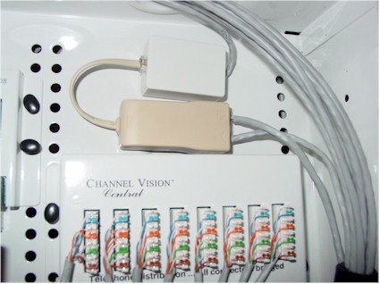
Figure 10: DSL filter installation detail
Network #3: DIY 19 Inch Racks
When I saw the pictures of “JustPlainJef”‘s down-and-dirty installation, I had a “why didn’t I think of that” reaction to his homebrew 19″ racks. Figure 11 shows what you can do with some L-brackets and leftover 2 X 4’s and sheathing.
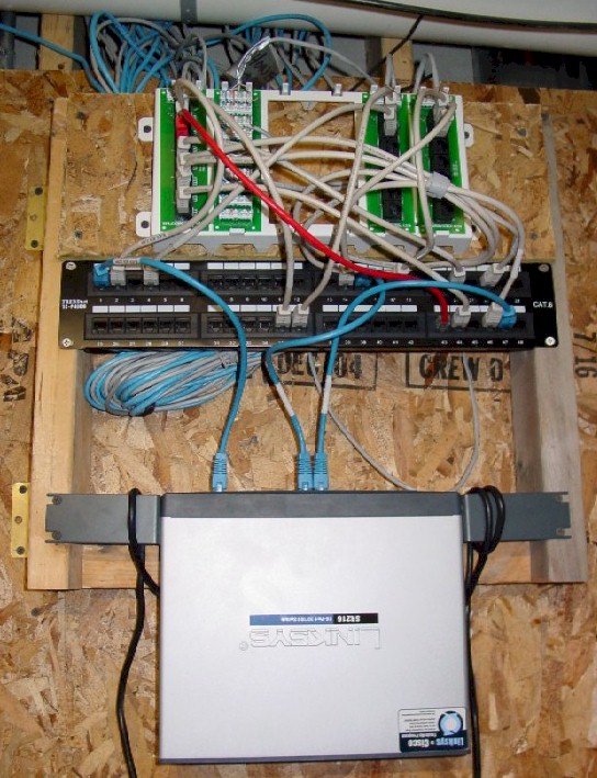
Figure 11: A creative 19 inch rack
(click image to enlarge)
Jef noted that the cable management is a work in progress – he’s since added cabling that uses 47 out of the 48 jacks on the patch panel – but everything works fine.
There are more pictures posted over at Jef’s site if you’d like to explore more of his very pragmatic installation.
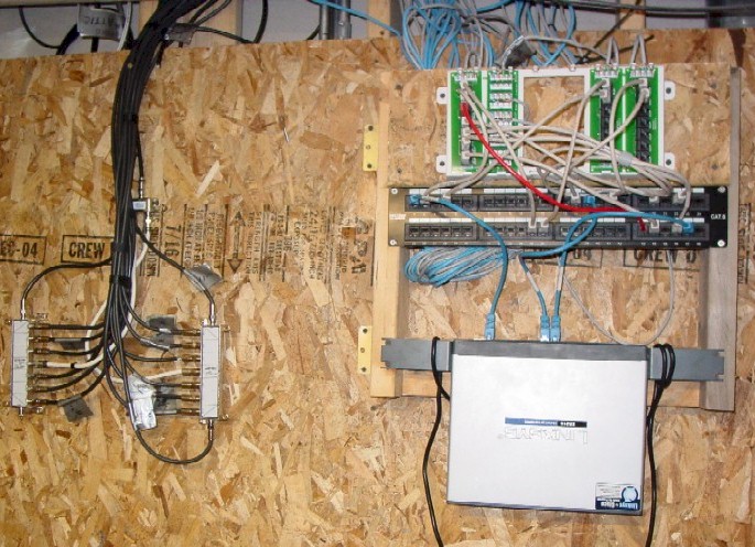
Figure 12: Data, phone and video distribution
(click image to enlarge)
Our thanks go to Chris, Mike and Jef, for sharing the fruits of their home-networking labors.