Introduction
As your network grows, you may have decided to use VLANs to improve network performance and/or network security. VLANs are a Layer 2 technology and are supported on many Layer 2 switches, such as the TPLINK TL-SG2216, TRENDnet TEG-160WS, and the NETGEAR GS108T.
A best practice with VLANs is to use different network addresses for devices in each VLAN. For example, you might use IP address ranges, also known as subnets, such as 192.168.1.0 for devices in VLAN 1 and 192.168.2.0 for devices in VLAN 2, and so on. One of the challenges with using a Layer 2 switch and VLANs with different subnets is your router needs multiple LAN interfaces or has to support VLAN tagging and trunking so you can route between VLANs.
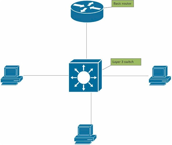
This is where a Layer 3 switch comes in handy. A Layer 3 switch can perform IP routing tasks as well as Layer 2 tasks such as VLANs. Moreover, a Layer 3 switch can typically route faster than a router, improving network performance. Futher, since the Layer 3 switch can route between VLANs, you can use a basic router that doesn’t support VLANs.
The OSI Model
The OSI model is a conceptual model that groups communication system functions into layers of abstraction. The Layer 3 that we refer to in this article is sometimes called the "Routing" layer.
| OSI Model | ||||
|---|---|---|---|---|
| Data unit | Layer | Function | ||
| Host layers |
Data | 7. Application | Network process to application | |
| 6. Presentation | Data representation, encryption and decryption, convert machine dependent data to machine independent data | |||
| 5. Session | Interhost communication, managing sessions between applications | |||
| Segments | 4. Transport | End-to-end connections, reliability and flow control | ||
| Media layers |
Packet/Datagram | 3. Network | Path determination and logical addressing | |
| Frame | 2. Data link | Physical addressing | ||
| Bit | 1. Physical | Media, signal and binary transmission | ||
In this article, I’m going to walk you through setting up a network with three VLANs, each using different subnets, and configuring a Layer 3 switch to route between those subnets. I’m going to use a basic small network router that doesn’t support VLANs, the Linksys WRT310N, and the recently reviewed NETGEAR M4100-D12G Layer 3 switch.
Before I do my configurations, I find it best to plan what I’m going to do. Write down how many VLANs you’re going to use, the numbers for each VLAN, and the IP address range (subnet) you’re going to use for each VLAN. Within each subnet, identify the addresses that will be used for the default gateway and DNS server(s). Also, determine if you’re going to use DHCP or static addressing in each VLAN.
Below is a chart with the details of my plan. I’ve set up three VLANs, identified my VLAN IDs, subnets, default gateway IPs, and DNS IPs. I choose these subnets and VLAN IDs as my network is already using the 192.168.199.0 subnet on VLAN 1. The IP address of 192.168.199.254 was not used, so I’m going to use that as a VLAN interface address on the Layer 3 switch. VLAN 7 and 8, along with the 192.168.7.0 and 192.168.8.0 subnets were also not in use on my network, thus they are available for me to use for this test. With this chart, I can now configure the network.
| VLAN ID | Subnet | Default Gateway/VLAN Interface IP | DNS |
|---|---|---|---|
| 1 | 192.168.199.0/24 | 192.168.199.254 | 192.168.199.1 |
| 7 | 192.168.7.0/24 | 192.168.7.254 | 192.168.199.1 |
| 8 | 192.168.8.0/24 | 192.168.8.254 | 192.168.199.1 |
Planning Table
Step 1
Before you configure the Layer 3 switch, create static routes in the gateway router to each of the new subnets. In this example, my gateway router uses a LAN subnet of 192.168.199.0, so I need to create static routes on the router to the 192.168.7.0 and 192.168.8.0 subnets.
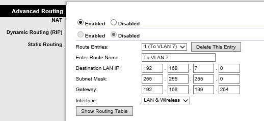
Static Routes on a Router
Note, some Layer 3 switches may support using routing protocols such as RIP or OSPF. If that’s the case, you might be able to enable the routing protocol on both the router and switch, and the routes will automatically be discovered. The M4100 does not support routing protocols, so I manually entered static routes.
Step 2
Log into your Layer 3 swtich management interface. The first step on the Layer 3 switch is to enable IP routing. On the M4100, IP routing is disabled by default. Enabling it is just a click as shown below.
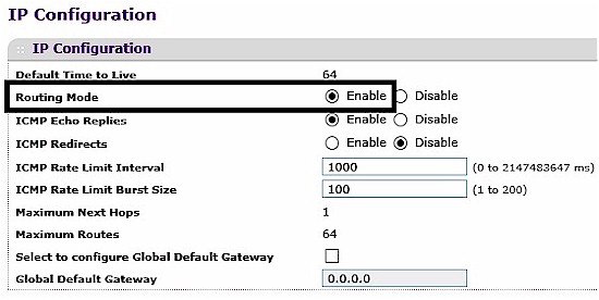
Enable IP Routing
Step 3
Create the VLANs on the Layer 3 switch and assign ports to each VLAN. As you can see below, I’ve added VLANs 7 and 8.
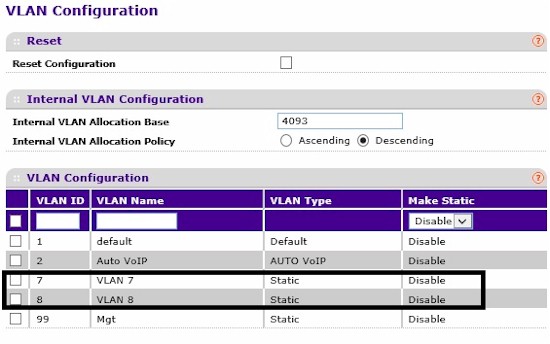
Create VLANs
I’ve also assigned ports to each VLAN…
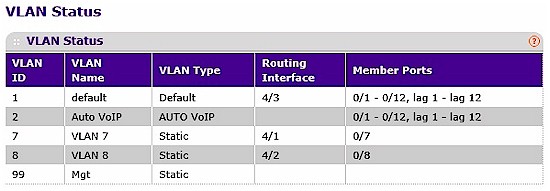
VLAN Ports
… and set the PVID on the ports to match their VLAN ID.
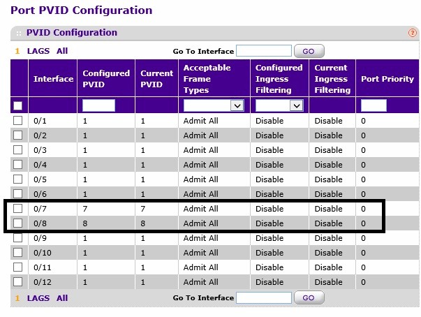
VLAN PVIDs
Note, I set the switch ports as untagged members of each VLAN as I’m not connecting to another VLAN aware device, thus I don’t need to use VLAN tagging.
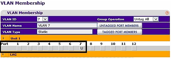
Untagged VLAN
Step 4
If your Layer 3 switch can function as a DHCP server, configure a DHCP server for each VLAN. The M4100 switch has DHCP server functionality, so I set up DHCP servers for VLANs 7 and 8. The screenshot shows my configuration for the DHCP pool for VLAN 7.
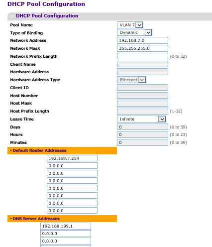
DHCP Pool
My DHCP server configurations for VLAN 8 are basically the same, but using the 192.168.8.0 subnet. I did not configure a DHCP pool for VLAN 1 on the switch, as my router already provides a DHCP server for VLAN 1.
When configuring a DHCP Pool, it is also important to configure an exclusion list. The exclusion list is a list of statically assigned IP addresses that you don’t want to be given out by the DHCP server, such as the Gateway or VLAN Interface IP address.
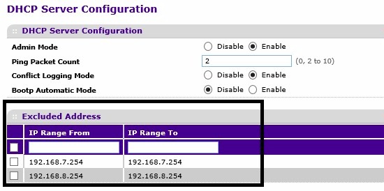
DHCP Exclusions
If your Layer 3 switch doesn’t provide DHCP server functionality, you can either statically address devices in each VLAN, or use a separate DHCP server. If you use a separate DHCP server, you may need to enable DHCP Relay on the Layer 3 switch so DHCP requests are forwarded to the DHCP server.
Step 5
Create VLAN interfaces for VLAN 7 and 8 on the Layer 3 switch as shown below. As you can see in the steps so far, the table I created at the beginning is providing all the values I need to complete my configuration.

VLAN Interfaces
Step 6
Create a default route from the Layer 3 switch to the gateway router. My default route is pointing all traffic not matching a specific route in the route table at my gateway router, 192.168.199.1.

Default Route
Step 7
This step may be different on some Layer 3 switches, it depends on whether the managment VLAN is routable. On the M4100, the managememt interface isn’t routable and it is configured by default to use VLAN 1. I have to make a few changes if I want VLAN 1 to be routable.
I connected my PC to port 7, which is now on VLAN 7 and logged into the switch through its VLAN 7 interface, 192.168.7.254. Shown below, I created VLAN 99 and changed the M4100’s management interface to VLAN 99 and gave it an IP address from an unused IP address range, 192.168.99.10. VLAN 99 is a “dummy” VLAN as I won’t be using it on my network.
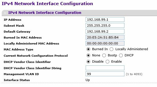
Management Interface
Step 8
Create the VLAN 1 interface on the switch. Now that VLAN 1 is not used for the management interface, you can create a routable interface for this VLAN 1. In the screen shot shown under step 5, I gave the VLAN 1 interface an address of 192.168.199.254 as planned from my chart.
Step 9
Connect your devices and test. Put a PC on each of the VLANs, make sure it gets an IP address in the appropriate subnet. (Note, you need to have an active device on each VLAN for the switch’s VLAN interface to be active.) Use the chart you created at the beginning and ping all the addresses listed, as well as ping an Internet address, such as google.com. Check the route table in your router and switch to ensure both have routes to all the subnets. Check the default route destination on the switch is set correctly.

Route Table
If all your tests have passed, you’ve successfully set up VLANs and inter-VLAN routing on a Layer 3 switch. Network performance should increase as you’ve now separated broadcast domains, yet you’re able to route between broadcast domains at near wire speed. Security of your network can now be more easily managed as you can implement filters to control traffic based on subnet addreses.
If your network isn’t working, go back to your chart. Make sure you’ve assigned the correct addresses on each VLAN. Also, go back to your router and make sure your static routes are properly configured. Most routers have a ping utility, verify your router can ping each of the switch’s VLAN interfaces.
Closing Thoughts
I used NETGEAR’s M4100 as my Layer 3 switch, but there are many other options out there, such as Cisco’s SG300 series switches. I reviewed the Cisco SG500-28P not too long ago, which also is a Layer 3 switch.
I hope this guide is helpful in growing and managing your network. The bottom line is a Layer 3 switch can make it easier to implement VLANs and separate subnets on your network without investing in a new router.
