Introduction
Photo courtesy of Wikipedia
Part 1 of this series provided an explanation of WLAN basics and described common wireless problem symptoms and their probable causes. Part 2 showed you how to perform a site survey to get information about your wireless environment, while Part 3 described the principles behind increasing wireless coverage and talked about improvements on the AP end. This time, I’m going to cover the hows and whys of upgrading antennas.
NOTE: Please read references to access points (AP) or wireless routers as applicable to both kinds of products unless otherwise noted.
Although it’s tempting to think that throwing amplifiers at the problem of weak signals will be a quick and “best” fix, experience has shown that using higher-gain antennas is often simpler and more cost-effective in improving problem WLANs. Consider the following points:
- Amplifiers boost both signal and noise. Although this isn’t really a problem in the transmit direction, amplified noise can swamp out a weak wireless client signal.
- WLANs are two way-systems. It does little good to have an Access Point with a strong transmitted signal if wireless clients don’t have equivalent range.
- For best results, amplifiers must be located as close as possible to the AP’s antenna to avoid losing the amplifier’s gain through loss in a long cable. This requirement can complicate an amplifier’s installation beyond the point where many home networkers will want to deal with it.
So let’s say that you’re convinced that using a higher-gain antenna is the way to go. Where do you start? Unless you use the trick of adding parabolic reflectors to your existing antennas, your AP’s antennas need to be attached via connectors.
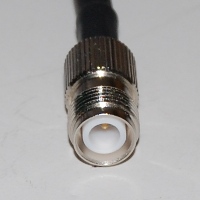
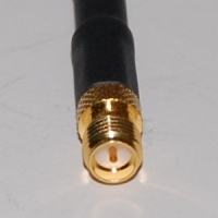
Many Linksys wireless routers, including its ubiquitous WRT54G, have upgradable antennas attached via RP-TNC connectors. Many of D-Link’s 802.11g wireless routers also have connectorized antennas, but use smaller RP-SMA connectors. Figure 1, which is taken from the Citrus Cables RF Connector Identification Chart, shows the jack version of both connectors.
 |
 |
|
RP-TNC Jack
|
RP-SMA Jack
|
Figure 1: Popular WLAN Antenna Connectors (not to scale!)
|
|
By the way, the “RP” in each connector-type’s name stands for “Reverse Polarity”. These are special versions of each connector type that have the gender of their center contact reversed from that of the non “RP” version. This is done to satisfy Part 15.203 of the FCC regulations, which says in part:
An intentional radiator shall be designed to ensure that no antenna other than that furnished by the responsible party shall be used with the device. The use of a permanently attached antenna or of an antenna that uses a unique coupling to the intentional radiator shall be considered sufficient to comply with the provisions of this section. The manufacturer may design the unit so that a broken antenna can be replaced by the user, but the use of a standard antenna jack or electrical connector is prohibited.
Translation: “We don’t want folks changing antennas on their own and possibly violating FCC specs, so manufacturers can’t use ‘standard’ connectors”. Something obviously got lost in the translation, however, since “RP” based antennas and cables are widely available, and it’s unlikely that the FCC is going to come knocking at your door to shut down your wireless LAN!
TIP: The entire FCC Part 15 Rules are located here.
Connectorized antennas were relatively common with 802.11g routers and APs. But for draft 802.11n gear, manufacturers are moving toward internal or hard-attached antennas. (See Where Have All the Antennas Gone?)
Hard-attached antennas don’t necessarily mean that you have to break out your soldering iron, however. Because draft 11n routers often have miniature UHF connectors inside (usually Hirose U.FL) to attach the radio board (or radio section of the main board) to the external antennas that are hard-attached to the case.
Figure 2 shows what U.FL connectors look like and this Wikipedia photo can get you really up close and personal with the connector.
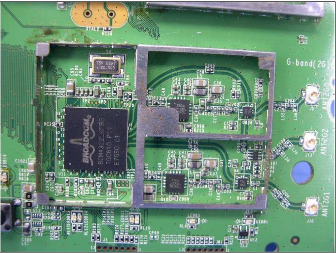
Figure 2: WRT610N 2.4 GHz radio with UF.L connectors
Another miniature UHF connector that you might run across in current products is Murata’s SWF series.
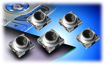
Figure 3: Murata SWF connector
It tends to be used on client cards, however, such as the Linksys WPC100 shown in Figure 4.
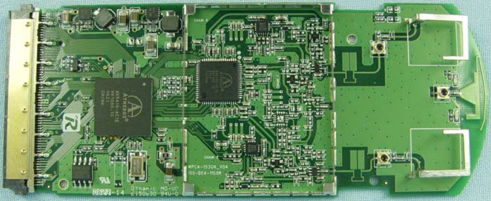
Figure 4: Linksys WPC100 board with Murata SWF connector
Of course, connectorized antennas are easier to deal with and changing them doesn’t involve voiding your router’s warranty. But if you’re really determined to move up to higher gain antennas, it’s nice to know that it will only involve buying (expensive) "pigtail" connectors vs. soldering.
Antenna Selection
Now that you have your old antenna removed and know its connector type, how do you select a new one? There are four main factors to consider:
Operating Frequency
Because of the way that radio waves work, antennas are designed to work over specific frequency ranges. Generally, the higher the operating frequency, the narrower the frequency range of an antenna.For 802.11b/g and the 2.4 GHz version of draft 802.11n, you need an antenna designed for 2.4GHz operation. This antenna won’t work for 802.11a purposes or the 5 GHz version of draft 802.11n, or course.
To complicate matters, draft 11n is also bringing back dual-band Wi-Fi, which throws the complication of dual-band (2.4 / 5 GHz) antennas into the mix. The concept of a dual-band antenna might seem to contradict my first statement above. But dual-band antennas are actually combinations of two single-band antennas into one assembly.
2.4 / 5 GHz antennas are hard to find, and high-gain versions even harder. This is why you tend to see business class APs with separate antennas for multiple radios.
Gain
As noted in Part 3, the simple dipoles that come with your AP have a gain of about 2.2dBi. And no, the two antennas on your AP don’t provide a total 4.4dBi of gain, but are there to support antenna diversity, which can improve your WLAN’s performance through a different technique.This is the main thing you’re trying to improve by changing antennas and you’ll probably spend the most time agonizing over this spec.
Radiation Pattern
This factor is as important as gain in determining whether a specific antenna is right for you. It determines the directivity or coverage area of the antenna, and if chosen incorrectly can make your wireless connection worse!Packaging/Mounting
It used to be that the antenna type determined the physical form-factor of an antenna. However, you can now get both omni and directional antennas in different physical forms. Especially handy for overcoming a spouse’s objections to your wireless improvement plans.
The art of antenna selection can get fairly involved when you’re trying to get a long-range outdoor link to work. But for indoor or short-range (house to workshop, across a street, etc.) use, selection is fairly easy if you keep two rules of thumb in mind:
Rule of Thumb #1: It takes at least a 6-dB (dBi) increase in gain to improve performance over what you get with a simple dipole antenna.
Rule of Thumb #2: The higher an antenna’s gain, the higher its directivity or narrower its area of coverage will be. This effect is similar to what happens with binoculars or telescopes. The higher the binoculars’ power, the narrower the field of view.
TIP: An antenna’s directivity is also commonly referred to as its “beamwidth”
With these rules in mind, let’s look at the types of antennas made for indoor use and their merits for specific applications.
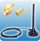
Wi-Fi Link 3 dBi cabled dipole |
Type: Dipole Gain: 3 dBi Pattern: Omni |
This type of antenna provides no additional gain over the dipoles that come with your wireless router.
But the cable allows more flexbility in antenna placement. This is most important if you are using a desktop PCI adapter. |
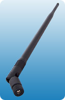
Wi-Fi Link 7 dBi dipole |
Type: Dipole Gain: 7 dBi Pattern: Omni |
This is a typical single-band omni-directional "rubber duck" type antenna that can directly replace similar antennas on your router. Note however, that higher-gain dipoles can be quite large and heavier than the ones that came with your router. So you may have to weight or screw down your router so that it doesn’t topple over! 9 dBi is about the highest gain you’ll find for this type and measures around 17" long! |
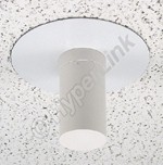
HyperLink HG2403CU
|
Type: Dipole Gain: 3 dBi Pattern: Omni |
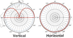
This antenna’s radiation pattern extends in all directions around it, but in a 90° “cone” below it. Good for keeping signals for escaping to upper floors, or above a roof. It provides no significant gain advantage over a dipole. Its primary use is for aesthetics and controlling signal leakage. |
|
|
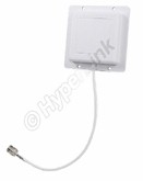
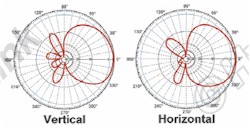
Type: Directional “panel” / “patch” Gain: 8 dBi Pattern: 75° horizontal, 65° vertical beamwidth |
This 4.5" square “patch” style has a directional pattern with relatively wide horizontal coverage for indoor use. Best suited for single-floor use, aimed at a central access point. |
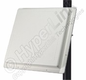
HyperLink HG2414P 2.4 GHz 14 dBi Flat Panel Antenna |
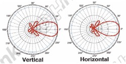
Type: Directional “panel” / “patch” Gain: 14 dBi Pattern: 30° beamwidth, horizontal and vertical |
The 14 dBi gain should provide noticeable performance improvement. But the 30% beamwidth makes this antenna very directional. This type would be used for building-to-building applications. |
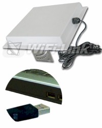
WiFi-Link U-Tenna 2.4 GHz Panel w/ USB adapter |
Type: Combination panel and USB adapter Gain: 14 dBi Pattern: Directional |
This is a combination of a 14 dBi panel antenna connected to a USB Wi-Fi adapter. It is used with wireless clients and allows the antenna to be placed up to 15 feet away without worrying about signal loss. It could be used indoors. But is better suited for building-to-building applications. |
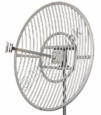
HyperLink HG2430G 2.4 GHz 30 dBi Grid Antenna |
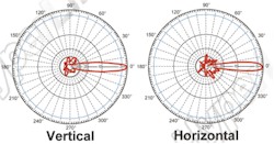
Type: Directional “panel” / “patch” Gain: 30 dBi Pattern: 5.3° beamwidth, horizontal and vertical |
This 30 dBi grid-style antenna is big (5′ diameter), heavy (35 lbs.) and for long-distance outdoor use only. Note the extremely narrow beam width, which requires very careful aiming and secure mounting. |
The choice of omnidirectional or “patch” types depends on antenna placement relative to the coverage area and any signal containment requirements. In general, omni-directional antennas are best for central access points. Directional antennas are better on the client side, aimed back at the central AP. They are also good for point-to-point wireless bridging applications.
Most of the antennas above are helpful for improving AP, wireless router and even wireless bridges. But improving a wireless client’s antenna is more difficult, because few adapters have connectors that allow other antennas to be attached. There are, however, some 802.11g USB adapters that support upgradeable antennas.
I reviewed the EnGenius EUB-362 EXT, which comes with a small 2 dBi dipole attached via an RP-SMA connector. It provided improved performance even with that small antenna and would do even better with a higher-gain antenna attached. If you’re looking for similar adapters for draft 802.11n, however, don’t bother because there aren’t any.
Before we leave the subject of antennas, let me show you why add-on laptop wireless cards have such poor performance. As most any laptop user knows, their WLAN adapter card is highly directional, but Figure 5 shows just how much!
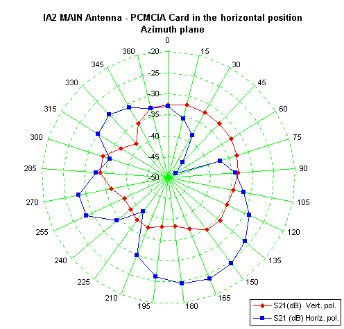
Figure 3: PC card antenna gain plot
From Antennas Enhance WLAN Security by Trevor Marshall
Used by permission
This plot shows the relative sensitivity of a typical PC card adapter, with the key points being:
- this is definitely not omni-directional performance
- the adapter would perform better if the laptop’s body were vertically oriented!
The reason for the second point is simple. Notebooks orient a WLAN adapter card’s antenna in a horizontal plane, while most access points’ antennas are vertically oriented. This simple fact itself accounts for the significant performance improvement from built-in WLAN notebook adapters because of their better orientation (usually vertical when the laptop screen is raised) and design (from not having to be squeezed into a 1 x 1.5 in space in the adapter itself).

