The Products
Updated 10/21/2010: Corrected WRT610NV2 and E3000 component info

Today’s announcements mark an important point in Cisco’s evolution of its approach to consumer networking product buyers. The company has established a new branding beachhead with the mommy-focused Valet line and is trying to make a clean break with its WRT past while imparting a subliminal "Expert" message with the Linksys E-line.
If the not-so-subtle message imparted by the image above isn’t enough to tell you which line you should be looking at, then maybe the soft, feminine blue color (my wife says it’s "French Blue") will provide a clue. At any rate, with plenty of similar Linksys-brand routers already on the shelves, how should you decide what to buy?
Figure 1 shows the new Valet products, which are single-band dual-stream N routers with 10/100 (M10) and Gigabit switches (M20). The Plus also has three internal antennas, the third used for receive only to goose gain a bit and try to eke out a bit more range.

Figure 1: Cisco Valet product line summary
The Valets are all about simplicity and just getting connected. You’ll find precious little technical information in the product literature. Hell, the products are even called "HotSpots", not routers, the better to identify with folks who may now be getting their Internet fix at Starbucks, Panera or even Mickey D’s, rather than brave setting up their own wireless network at home.
Figure 2 shows the E-series lineup, which includes single, selectable dual-band and simultaneous dual-band models, along with a Linux-based offering. These are clearly the choice for those don’t-need-no-steenking-Easy-Setup-USB-key!
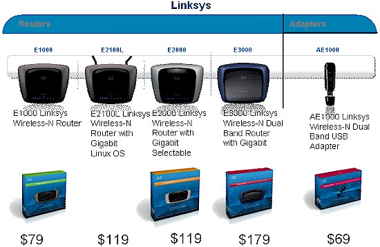
Figure 2: Linksys E-series product line summary
This line is intended to replace the current WRT series routers. Models include:
- E1000 Wireless-N Router (MSRP: $79.99)
Entry-level single band with 10/100 Ethernet ports - E2000 Advanced Wireless-N Router (MSRP: $119.99)
Single-radio dual-band with Gigabit Ethernet ports - E2100L Advanced Wireless-N Router with Linux OS (MSRP: $119.99)
Single band with 10/100 Ethernet ports, external upgradeable antennas, UPnP AV server and USB port for storage sharing aimed at fans of alternative router distros like DD-WRT, OpenWRT, etc. - E3000 High-Performance Wireless-N Router (Dual-Band) (MSRP: $179.99)
Two-radio, dual-band
with Gigabit Ethernet ports, UPnP AV server and USB port for storage sharing
Cisco told me that the rest of the WRT models, including G-only products, will be sold until inventory is exhausted. So it’s likely you’ll see both WRT and E-series for sale for awhile, depending on how fast wireless networking stuff moves at your local retailer.
But marketing spin aside, is there anything in these products that should make you run out to replace any Linksys N routers you already own?
If you want to cut to the chase, just take a gander at Table 1. It lists the Valet and E series products, their WRT-series equivalents and key devices used. Most of this information was obtained by peering at the often fuzzy photos in the FCC ID internal photo filings. As near as I can tell, it’s accurate. But if I’ve made any mistakes, please let me know and I’ll update the table.
Updated 10/21/2010: Corrected WRT610NV2 and E3000 CPU info
| New | Old | Chipset |
|---|---|---|
| Valet (M10) | WRT160N (V3) | – Broadcom BCM4716 Intensi-fi XLR 802.11n 2.4 GHz Router System-on-Chip – Switch: Broadcom BCM5325 |
| Valet Plus (M20) | WRT310N (V2) | – Broadcom BCM4716 Intensi-fi XLR 802.11n (2.4/5 GHz) Router System-on-Chip – Switch: Broadcom BCM53115 |
| E1000 | WRT160N (V3) | – Broadcom BCM4716 Intensi-fi XLR 802.11n 2.4 GHz Router System-on-Chip – Switch: Broadcom BCM5325 |
| E2000 | WRT320N | – Broadcom BCM4717 Intensi-fi XLR 802.11n (2.4/5 GHz) Router System-on-Chip – Switch: Broadcom BCM53115 |
| E2100L | WRT160NL | – CPU: Atheros AR9130 400MHz Wireless Network Processor – Switch: Realtek RTL8306SD – BB/MAC: In AR9130 – Radio: Atheros AR9102: Single-band 2×2 MIMO 802.11n Radio |
| E3000 | WRT610N (V2) | – CPU: Broadcom BCM4718 @ 480 MHz – Switch: Broadcom BCM53115 -5 GHz: In BCM4718 -2.4GHz: Broadcom BCM4322 Intensi-fi Single-Chip 802.11n Transceiver |
Table 1: Valet, E-series and WRT comparison
The table originally had four colums, so that I could separately list the chips used in both the old and new products. But it turns out that I didn’t need the fourth column, because the "old" and "new" products use the same chipsets, and it looks like, even the same boards.
Basically, the "new" E-series products are rebrandings of their WRT-equivalents. And aside from the girlie color of the Valet routers’ enclosures, those products are WRT-series copies, too.
I’m glad to see that Cisco has not included any single-stream N routers in their new lineups, for reasons I’ve already explained. Of course, they could reappear as Cisco adds to the E-series line.
Broadcom is the big winner in this product line transition, since their devices populate five of the six new products. Cisco may flirt with other wireless chipset vendors from time to time. But they always seem to come back to Broadcom.
That’s really it in a nutshell. No need to rush out and buy any of what was introduced today if you’re already happy with what you have. And if you are in the market for a new N router, then you can buy either the new stuff or the models they are replacing. I’d keep an eye out for discounts on the WRT models, though, since retailers may be wanting to just clear them out and reduce their inventory.
If you’d like a photo tour of the routers’ innards, just go to the next page.
The Details
 FCC photos usually show pre-production samples. Shipping production product may differ.
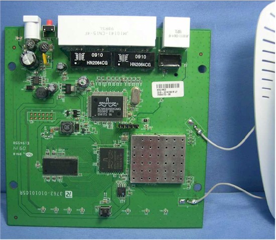
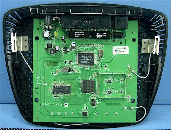
Figure 3 shows the Valet M10, still connected to its two antennas.
Figure 3: Cisco Valet M10 board
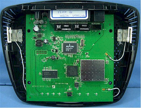
Figure 4 shows its WRT160N (V3) equivalent. Looks like the same board to me!
Figure 4: WRT160N V3 inside
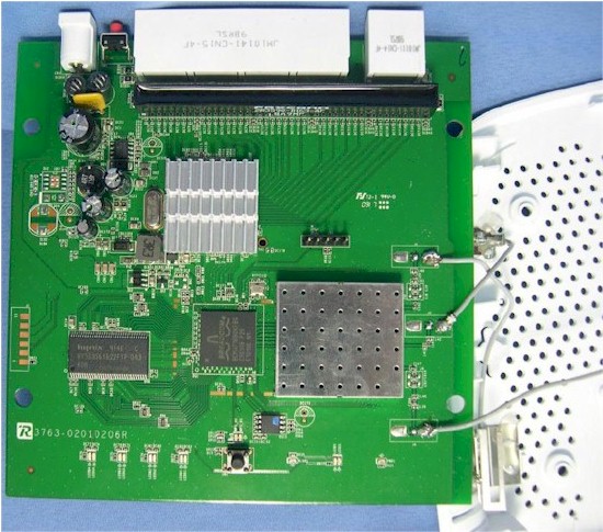
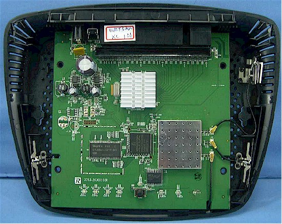
Moving along to Figure 5, we see the Valet Plus M20 board. The heatsink hides the Broadcom BCM53115 Gigabit switch, but I know it’s there!
Figure 5: Cisco Valet Plus M20 board
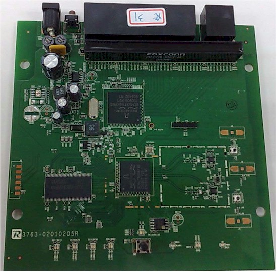
Figure 6 shows the Linksys WRT310N (V2) board, which looks mighty similar. The heatsink on the BCM53115 switch was removed for this photo. Notice the resemblance?
Figure 6: Linksys WRT310N V2 board
Since both the M10 and M20 use the same Broadcom BCM4716 Intensi-fi XLR 802.11n 2.4 GHz Router System-on-Chip, how does the M20 get three antennas out of the same chip that handles only two on the M10?
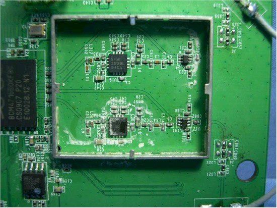
Figure 7 shows the M10’s RF section detail, which uses two SiGE SE2528L 2.4GHz Power Amplifier with Power Detectors, with receive / transmit switches for each antenna.
Figure 7: Cisco Valet M10 RF section detail
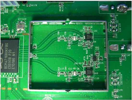
Figure 8 shows the M20’s RF section, which appears to have the BCM4716 receive and transmit traces for each antenna going to S2364164 devices (sorry, Google came up empty on those). Traces from those devices then feed into a third antenna, which serves both receive chains. As mentioned earlier, the third antenna is used for receive only, to provide a bit more gain to try to enhance range.
Figure 8: Cisco Valet M20 RF section detail
The Details – more
Moving on to the E series, Figure 9 provides a look at the E1000‘s board. You should be pretty familiar with this design by now, having seen it for both the M10 and WRT160N V3!
Figure 9: Linksys E1000 board
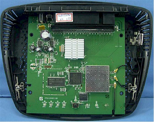
Figure 10 shows one of the photos from the E2000‘s FCC ID internal photos document.
Figure 10: Linksys E2000 board
While Figure 11 shows one from the WRT320N‘s FCC document. I think the photos speak for themselves! Download the documents for the WRT320N and E2000 if you think I made a mistake! (You may need to rename the files using a.pdf extension.)
Figure 11: WRT320N inside
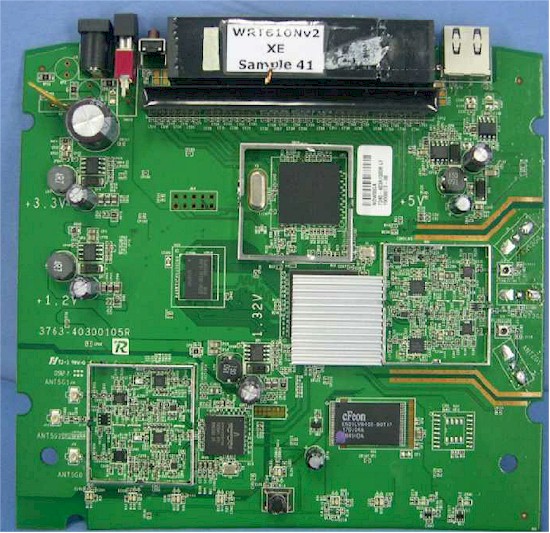
A similar deja vu occurs when checking out the E3000‘s internal FCC photos, one of which is shown in Figure 12. I’m not going to bother showing the duplicate in the WRT610N V2’s FCC document, for obvious reasons!
Figure 12: Linksys E3000 board
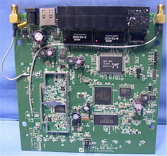
Finally, the separated-at-birth trend continues for the E2100L and WRT160NL, so I’m just showing the photo from the E2100L’s FCC file in Figure 13. You can pull the WRT160NL’s FCC file and check for yourself.

