Introduction
Updated 12/06/2012: Add draft 11ac client info
Updated 11/29/2011 Clarify test clients, again.
Updated 11/7/2011 to reflect new dual-stream N test client
This article describes the wireless test procedure for products tested after July 24, 2011.
For wireless products tested between June 19, 2008 and July 23 2011, see this article.
For wireless products tested between March 2007 and June 19, 2008, see this article.
For wireless products tested after November 2005 to before March 2007, see this article.
For wireless products tested after October 1, 2003 to before November 2005, see this article.
For wireless products tested before October 1, 2003, see this article.
Our six location wireless test method has served us well for the past three years. But with six locations, two test runs per band (20 MHz and 40 MHz bandwidth) and two bands in many products, it takes hours to to excute just one test run. Add in time for debugging, rerunning tests, etc. and it can take half a day just to test the wireless portion of a wireless router.
Now that dual-band three stream N routers are starting to appear, the number of tests required doubles yet again since we now need to run a full suite of tests using both two and three-stream enabled clients. Clearly, if we’re going to get through the growing backlog of wireless products piling up on the SmallNetBuilder test bench, something has to change.
Our solution is to drop back to using four test locations. So let’s review the test environment and new locations.
Environment
The Test Environment is an approximately 3300 square foot two-level home built on a hillside lot with 2×6 wood-frame exterior walls, 2×4 wood-frame sheetrock interior walls, and metal and metalized plastic ducting for the heating and air conditioning system.
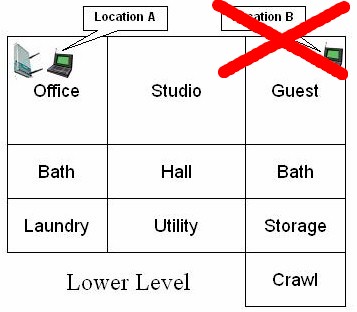
Figure 1 shows a simplified layout of the lower level and one of the four test locations. Discontinued Location B from the previous six location method is shown for reference.

Figure 1: Lower Level Test Locations
Note that the Laundry, Utility, Storage and Crawl(space) areas are below grade, but the rest of the rooms on the lower level have daylight access.
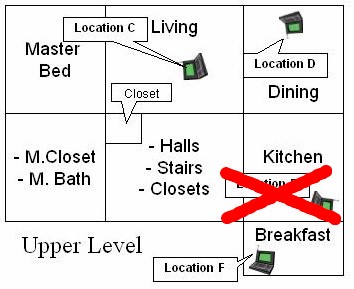
Figure 2 shows the upper level layout and the remaining three test locations.

Figure 2: Upper Level Test Locations
We feel comfortable dropping Location B because its signal level and resulting throughput is similar enough to Location C. Similarly, the results from Location E are close enough to those from Location F that little insight into a product’s performance is gained from testing in both locations.
Put another way, if a product works in Location C, it’s going to perform similarly in Location B. And the throughput measured in Location F is pretty much going to tell the tale for Location E.
The lower-level corner office is not the best location for placing a wireless router or access point for whole-house coverage, but serves the purpose well for pushing products to their limits. Note that the orientations of the icons for the AP and notebooks indicate the orientation of the test notebook in all locations except Location F.
Signal levels in Location F are so low that an attempt is made to orient the notebook for peak throughput. This generally means the back of the notebook screen (where the antennae are located) is pointed toward the product under test in Location A.
Here are descriptions of the four test locations:
- Location A: AP and wireless client in same room, approximately 6 feet apart.
- Location C: Client in upper level, approximately 25 feet away (direct path) from AP. One wood floor, sheetrock ceiling, no walls between AP and Client.
- Location D: Client in upper level, approximately 35 feet away (direct path) from AP. One wood floor, one lower level sheetrock wall, sheetrock ceiling between AP and Client.
- Location F: Client on upper level, approximately 65 feet away (direct path) from AP. Four to five interior walls, one wood floor, one sheetrock ceiling between AP and Client.
Test Description
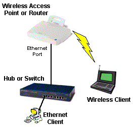
Ixia’s IxChariot network peformance evaluation program is used with the test configuration shown in Figure 3 to run tests in each of the test locations.
Updated 11/28/2011
All testing is done with an Intel Centrino Ultimate-N 6300 half PCIe card in a Lenovo x220i ThinkPad with three antenna option, running Windows 7 Home Premium SP1 (64 bit), unless otherwise noted.
Dual-stream N testing of three-stream N products is done using an Intel Centrino Advanced-N 6200 mini-PCIe card in a Acer Aspire 1810T notebook running Windows 7 Home Premium SP1 (64 bit), unless otherwise noted. A different test client is needed because there is no way to force a three-stream N client into two-stream mode.
Updated 12/6/2012
For draft 11ac products, there are no standard test clients at this time capable of supporting 1.3 Gbps link rates. So we test using either a second router/AP set to non-WDS bridge mode or a dedicated wireless bridge product from the same manufacturer. The exact test conditions are described in each review.
Note: Prior to 7 November 2011, an Intel 5300 with an unconnected third antenna was used as the standard test client. This was replaced by the Intel 6200 because the unconnected third antenna on the 5300 card could cause erratic dual-stream test results with some three-stream routers.

Figure 3: Wireless test setup
All routers / APs are generally reset to factory defaults and placed on a non-metallic desk approximately six feet from an outside wall in the lower level Office.
All testing is done with a WPA2 / AES secured connection.
No other wireless networks or sources of in-band interference are active during testing. (The home is in the middle of a wooded seven acre lot, so neighboring WLANs are not a problem.)
On wireless routers, all testing is done on the LAN side of the router so that the product’s routing performance does not affect wireless performance results, i.e. the Ethernet client is connected to a router LAN port.
At each test location, the IxChariot Throughput.scr script (which is an adaptation of the Filesndl.scr long file send script) is run for 1 minute in real-time mode using TCP/IP in both uplink (client to AP) and downlink (AP to client) directions.
The only modification made to the IxChariot script is to change the file size from its default of 100,000 Bytes to 1,000,000 – 5,000,000 Bytes for draft 802.11n products. File size is adjusted as needed to obtain enough resolution to see large throughput dropouts, but also to provide some plot smoothing for readability.
Tests are generally run once. But if a test run reveals unusually high throughput variation or low throughput, tests are repeated so that we can determine whether the bad run was an anomaly. If a test is repeated, the best of the runs is used.
Generally, tests are run in all locations before changing frequency band, bandwidth setting or stream configuration.
