Introduction
Amped Wireless is the second company to get a QCA-based MU-MIMO enabled AC2600 class router to market. Nicknamed "Athena", the RTA2600 High Power AC2600 Wi-Fi Router with MU-MIMO is now the new top of Amped’s router lineup.
To recap, AC2600 class routers are the latest generation of 4×4 routers, with AC2350 / AC2400 being the first. Both old and new 4×4 routers support a 1733 Mbps maximum 5 GHz link rate. But the new generation gets a bump from 600 to 800 Mbps maximum link rate on the 2.4 GHz side due to QAM-256 support, a by-product of using the same radio chip as the 5 GHz side. 1733 + 800 = 2533, which all wireless router makers have decided to generously round up to justify the AC2600 classification.
The more significant feature of the AC2600 class, however, is that it has MU-MIMO support. MU-MIMO is a technology that improves total throughput use, but requires clients that also support it. As of right now, there are only a handful of MU-MIMO enabled clients and manufacturers aren’t going out of their way to rush to market with more. So if you buy any MU-MIMO enabled router today, you’re unlikely to be able to utilize its key claim to fame.
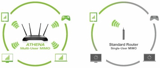
MU-MIMO
By the way, first generation 4×4 routers all use Quantenna’s QSR1000 4×4 radio, which, as of this writing, still does not support MU-MIMO.
Getting back to Athena, the rear of the router has four RP-SMA antenna connectors, reset switch, WPS button, power connector, 4 Gigabit LAN ports and Gigabit WAN port. All Ethernet ports have their own embedded link / activity LEDs.
There is also a USB 2.0 port for storage sharing and main power and LED on / off switches. The inset shows a USB 3.0 port, situated near the Athena’s front right corner (facing front). Note, however, that there is no physical Wi-Fi On / Off switch.

Amped Wireless RTA2600 connectors and ports
The front panel has all blue indicator lights as shown in the callout graphic below. Like Amped’s other routers, the panel markings are tiny and a light grey color that makes them hard to make out. LAN port indicators show link and activity, but don’t change color to indicate link rate.
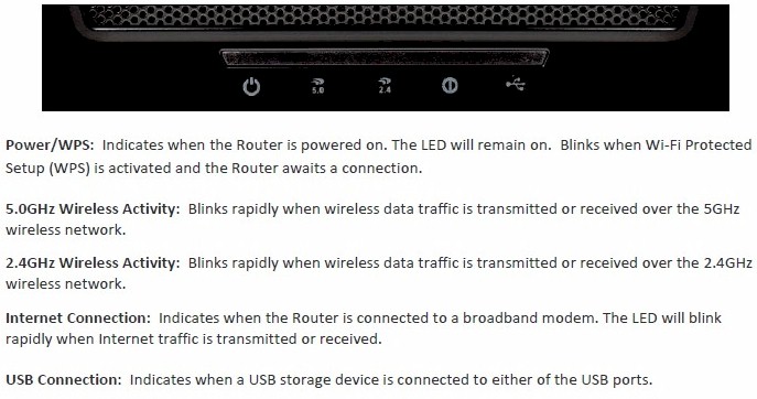
Amped Wireless RTA2600 lights
The bottom of the router has plenty of vent slots, but the top has vent slots concealed under the perforated U surrounding the raised bump at the center rear. The front corners of the Athena also have the vent-slots-behind-perforated-grille design repeated.
The router is designed to sit flat on a desk, but can be wall mounted either horizontally or vertically with centrally positioned four-way screw slots.
Inside
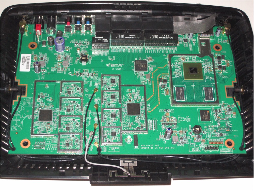
Amped didn’t put a short-term hold on its FCC ID docs, so I didn’t have to open the router for component identification. The first picture shows the main board out of its shell, but with RF cans intact. There are no heatsinks removed for this picture.
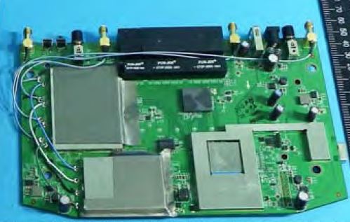
Amped Wireless RTA2600 inside
Here’s a closer picture with the cans removed. It’s still not clear enough for component ID. But the FCC internal pictures file had close-ups of all key parts.
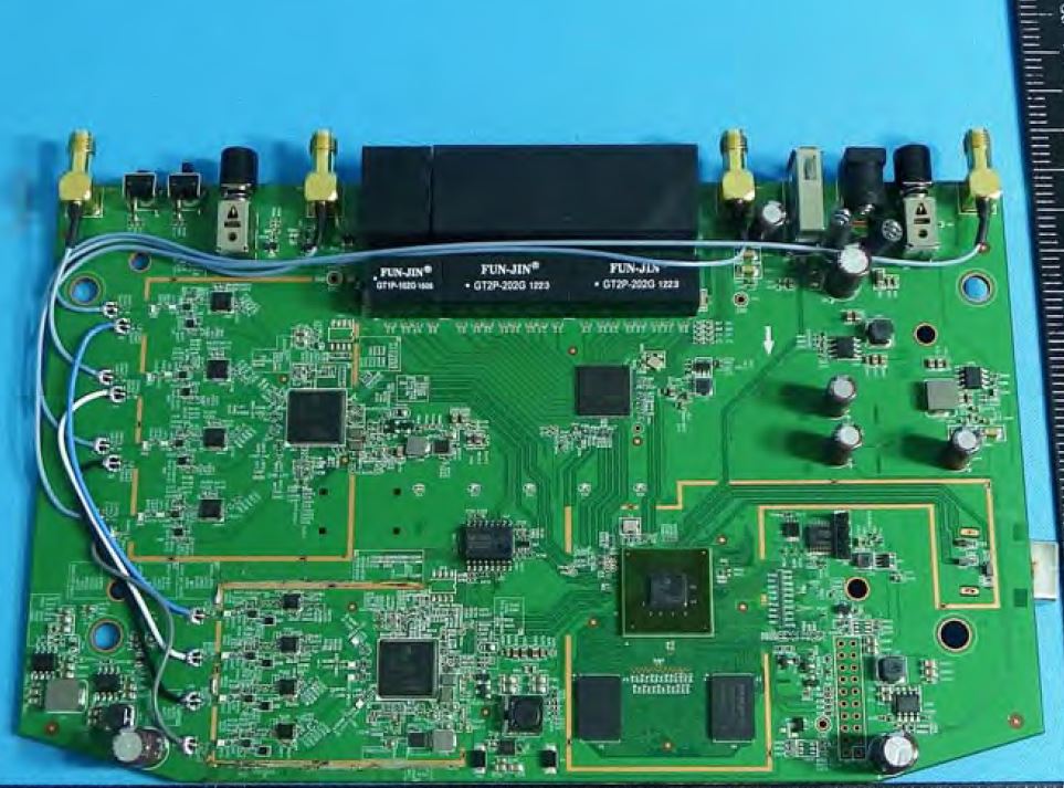
Amped Wireless RTA2600 board
Here’s the Linksys EA8500 board—the first AC2600 router released—for comparison.
Linksys EA8500 inside
Key components for both products are summarized in Table 1. There is only one subtle difference in key components. Amped opted to use the QCA9990 radio vs. Linksys’ choice of the QCA9980. QCA describes the 9980 as aimed at router and gateway designs while the 9990 is for enterprise access points, but doesn’t detail the differences.
| Amped Wireless RTA2600 | Linksys EA8500 | |
|---|---|---|
| CPU | Qualcomm dual-core IPQ8064 Internet Processor @ 1.4 GHz | Qualcomm dual-core IPQ8064 Internet Processor @ 1.4 GHz |
| Switch | Qualcomm Atheros QCA8337 | Qualcomm Atheros QCA8337 |
| RAM | 512 MB | 512 MB |
| Flash | 128 MB | 128 MB |
| 2.4 GHz Radio | – QCA9990 4-stream 802.11ac MU-MIMO radio – Skyworks SE2623L 2.4 GHz power amp (x4) |
– QCA9980 4-stream 802.11ac MU-MIMO radio – Skyworks SE2623L 2.4 GHz power amp (x4) |
| 5 GHz radio | – QCA9990 4-stream 802.11ac MU-MIMO radio – Skyworks SKY85405 5 GHz power amp (x4) |
– QCA9980 4-stream 802.11ac MU-MIMO radio – Skyworks SKY85405 5 GHz power amp (x4) |
Table 1: Component summary
Feature Summary
Here is a list of the RTA2600’s features.
Routing
- Static and Dynamic IP, PPPoE , PPTP and L2TP WAN connections
- MAC address cloning
- MTU Adjustment
- DHCP Server, range setting, lease time setting, and default domain
- DHCP Client list
- DHCP reservation
- Virtual Server entry for single or multiple ports with TCP, UDP or all protocols forwarded. Enable/disable for each entry.
- Port filtering – can set individual or range of incoming ports. Allows you to enable or disable TCP and UDP ports on network devices.
- Four level priority-based download QoS control. Bandwidth rules list based on IP or MAC address, port range and protocol
- DMZ Host
- UPnP enable/disable
- DDNS support for Dyndns (www.dyndns.org)
- NAT enable/disable
- RIP 1/2 dynamic routing
- Static routes
Security
- VPN Passthrough enable/disable for PPTP and IPsec
- DoS (denial of service) enable/disable
- Enable UDP Flood filtering (with settable threshold)
- Enable TCP-SYN Flood attack filtering (with settable threshold)
- Ignore Ping Packet from WAN port
- Remote Management on WAN enable/disable
- Block all network access by MAC and IP address
- URL filtering (applies to all users, HTTPS not blocked)
- Internet access control – Rule based access control for host (domain name or IP address)
Wireless features
- WEP, WPA / WPA2 Personal and Enterprise (RADIUS) support
- 4 guest wireless networks per band
- Wi-Fi Protected Setup (WPS) support, pushbutton and PIN
- Auto and manual channel set
- SSID broadcast enable/disable
- Enable/disable wireless
- Beacon interval, RTS threshold, Fragmentation Threshold adjustments
- Wireless MAC address filtering (allow or deny based on MAC address)
- WMM disable
- Short GI disable
- Wireless access schedules
- 5 GHz Wireless modes: a, a+n, a+n+ac (default)
- 2.4 GHz Wireless modes: b, b+g, b+g+n (default)
- 5 GHz channel width 20MHz/40MHz/80MHz
- 2.4 GHz channel width 20MHz/40MHz
- 5 GHz channels: 36, 40, 44, 48, 149, 153, 157, 161
- 2.4 GHz channels: 1-11
- Transmit power adjust, 15%, 35%, 50%, 70% and 100%
- Wireless network statistics, packets sent/received, active associated clients
Storage features
- SMB file sharing (no user accounts)
- FTP server. Can set port and control anonymous FTP and anonymous write protection. No secure FTP
As I checked Athena’s features against the list compiled for the RTA1750, I came across numerous changes. Gone are IPv6 or VLANs support as well as any control of remote administration. QoS features have switched from being bandwidth based for both internet up and downlink to four-level priority based for downlink only.
URL (website) filters are still supported, but don’t affect secure (HTTPS) sites. Blocks apply to all users, with no "trusted" users available. Access to specific web services can be controlled via firewall port filters, but filters apply to all users.
Storage features remain basic, with no media or printer sharing, only SMB and FTP. Sharing via secure FTP is also not supported.
The admin GUI’s look and feel hasn’t changed. It still has the same green and black motif and general organization.
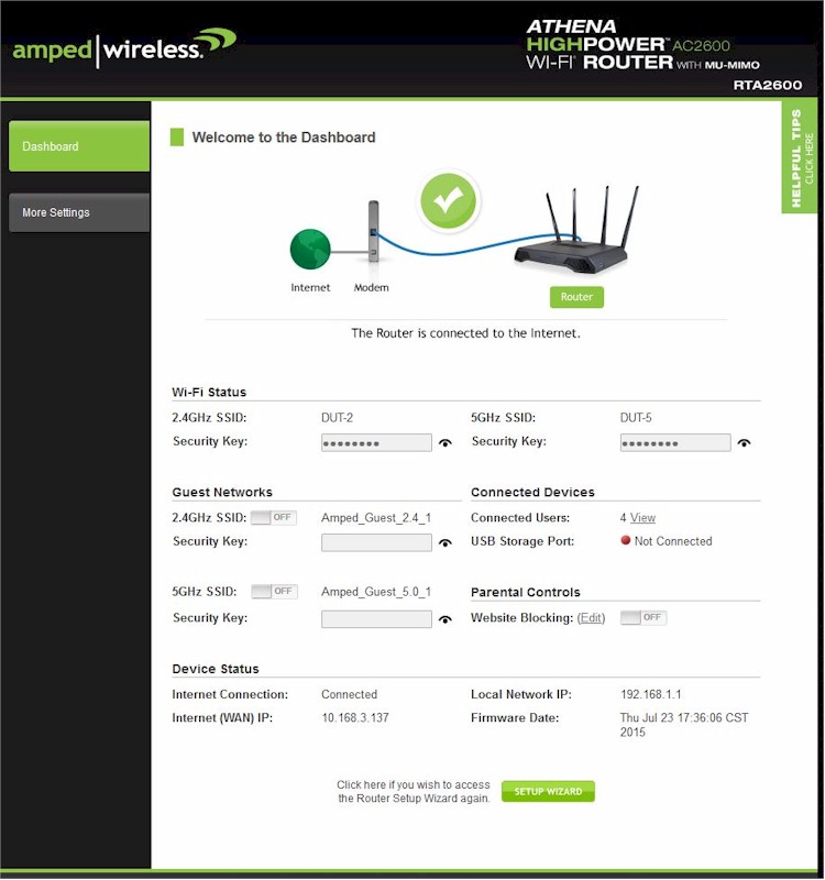
Amped Wireless RTA2600 Dashboard landing page
A few wireless features changes are worth noting. You can no longer set transmit rate, but can still control wireless mode and channel bandwidth on both radios. Curiously, WMM disables are shown on both radios, but they are greyed out. The 5 GHz radio Basic Settings now sport transmit beamforming and MU-MIMO enables (both are default enabled).
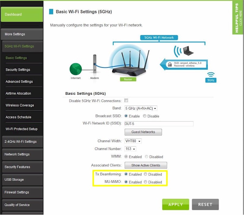
Amped Wireless RTA2600 5 GHz Basic Wireless settings
In what I believe is a first for Amped, Athena has Airtime Allocation controls. Here’s the explanation from the online help:
Airtime Allocation (also known as Airtime Fairness) is the intelligent allocation of available Wi-Fi Airtime among connected devices Wi-Fi airtime can be allocated by the entire Wi-Fi network or SSID, or inidvidually by each connected device. For example, if your network included a main network for your home and a guest network for your guests, the main network can be set with a larger allocation to ensure that your home connected devices get the most bandwidth while your guests that connect to your guest network just enough bandwidth without degrading your main network performance. Another example can be if you have a media streaming device that requires a lot of bandwidth to ensure seamless video streaming, that device can be prioritized so that it gets more airtime than other devices.
The total allocation must always equal 100%. Please adjust the airtime allocations accordingly.
The only other routers I’ve seen expose Airtime Fairness controls are NETGEAR, but with just a simple enable/disable. We’ll take a look at how well this works later.
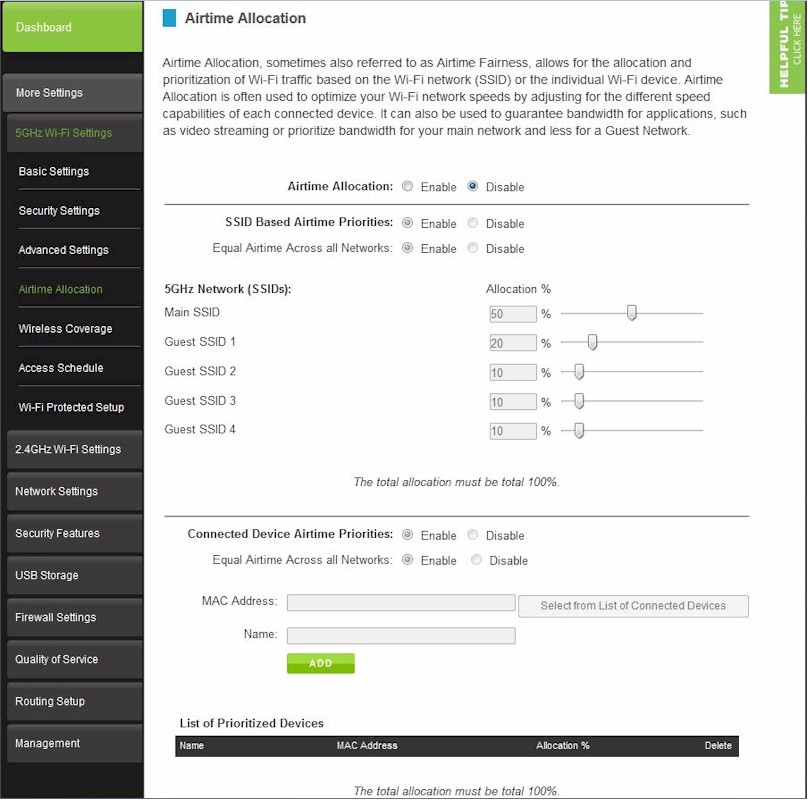
Amped Wireless RTA2600 Airtime Allocation settings
In all, the Athena’s feature set feels a bit weak for a top-of-line router, especially when compared to the smörgåsbord of features found in ASUS routers. If you want to explore Amped’s router feature set further, check the R1000G and RTA1750 reviews and their galleries.
Storage Performance
The summary graphic below from the Router Charts shows all 4×4 routers—both AC2350 / 2400 and AC2600—we’ve tested with our standard procedure with USB 3.0 connections and both FAT32 and NTFS drive formats. It’s interesting to note the difference in storage performance between the Linksys EA8500 and Athena. Both use the same devices, yet the EA8500 yields around 2X more storage throughput than Athena.
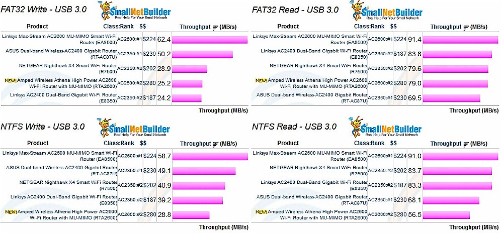
Storage Performance Comparison – USB 3.0
Routing Performance
Updated 12/16/15 Router performance retest due to measurement process error
Routing throughput was measured using our standard router test process with the router loaded with 1.43 firmware. Table 2 summarizes the results and includes the Linksys EA8500 for comparison. Again, it looks like the EA8500 beats Athena on most benchmarks. Maximum simultaneous connections didn’t make it up to the 30,000 connection level, beyond which we consider all products equal.
| Test Description | Amped RTA2600 | Linksys EA8500 |
|---|---|---|
| WAN – LAN | 613 | 702 |
| LAN – WAN | 711 | 805 |
| Total Simultaneous | 734 | 1493 |
| Maximum Simultaneous Connections | 16,340 | 35,320 |
| Firmware Version | 1.43 | 1.1.3.166845 |
Table 2: Routing throughput
The IxChariot unidirectional composite plot for the RTA2600 shows pretty stable throughput in each direction. The higher uplink throughput is consistent from product to product and likely a test method artifact.
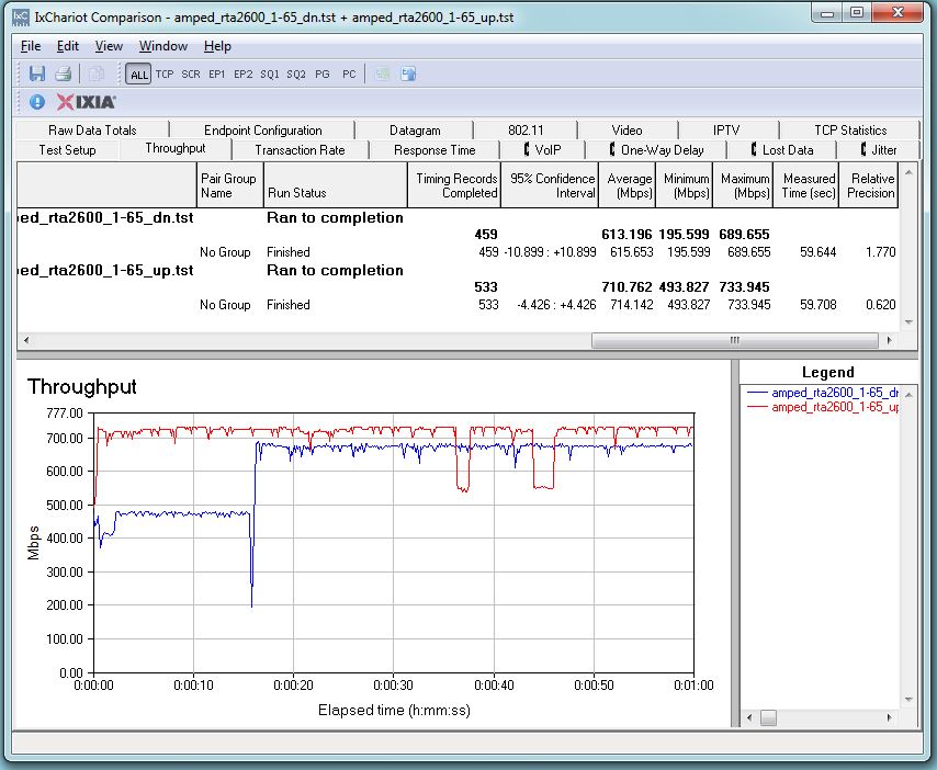
Amped Wireless RTA2600 routing throughput unidirectional summary
The RTA2600 simultaneous up/downlink benchmark plot shows the usual jump near the start due to IxChariot’s Nagle’s algorithm implementation. Once that settles down, there’s high throughput variation in both directions, with downlink coming up with a higher total average. The RTA2600 is one of the few routers we’ve tested recently that does not have total simultaneous throughput over 1,000 Mbps.
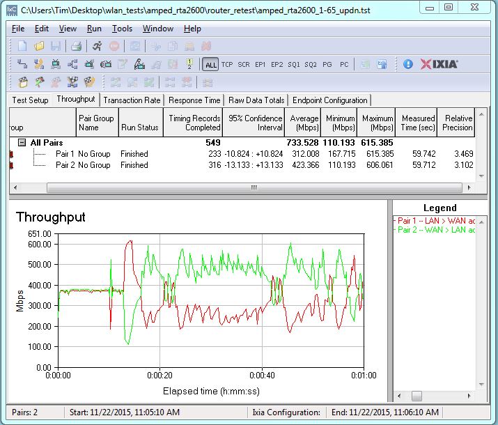
Amped Wireless RTA2600 routing throughput bidirectional summary
Wireless Performance
The RTA2600 is not Wi-Fi Certified (Amped does not Wi-Fi Certify any of its products). It was tested using the Revision 8 Wireless test process with 1.43 firmware loaded. The router comes with WPS enabled. I connected a Windows 10 notebook to the router’s 5 GHz SSID and was prompted for WPS PIN with a pushbutton alternative. A pushbutton session quickly resulted in a WPA2/AES connection, but with a very weak password (wireless) that is the same for both bands and not router unique. WPS has settings pages for both radios and can be disabled.
The router defaults to different, but not router-unique SSIDs (Amped_Athena_2.4 & Amped_Athena_5.0), auto channel select for each radio and 80 MHz bandwidth set for 5 GHz and 40 MHz bandwidth for 2.4 GHz.
For performance testing, the router was first reset to factory defaults. The 2.4 GHz radio was set to Channel 6 and 20 MHz only bandwidth mode. The 5 GHz radio was set to Channel 153 and left in 80 MHz channel width to enable 802.11ac link rates. The AC1900 class NETGEAR R7000 bridge mode standard test client was connected using WPA2/AES encryption.
Our standard practice is to center the router under test’s antennas on the turntable, both front-to-back and side-to-side in the chamber. This method is intended to keep maximum distance between the router under test and chamber antennas as the router rotates during test.
The Benchmark Summary below shows the average of all wireless throughput measurements made over the tested attenuation range.
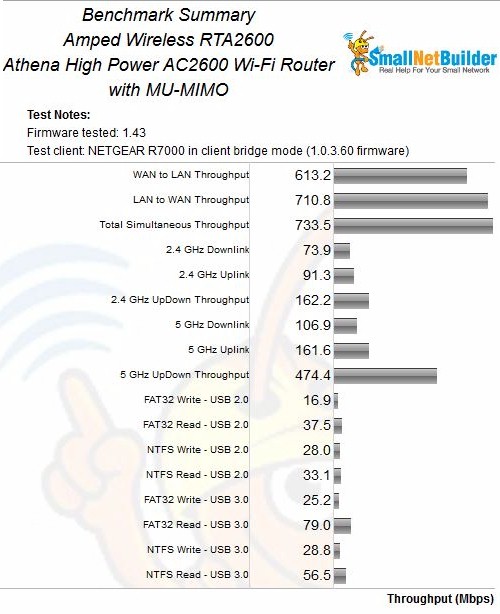
Amped Wireless RTA2600 Benchmark Summary
Although the Athena and Linksys EA8500 are classed separately for ranking purposes, it’s fair to compare them with AC2350 class 4×4 routers due to the use of an AC1900 standard test client. So I included the two top-ranked routers from that class, the ASUS RT-AC87U and NETGEAR R7500 Nighthawk X4 along with the EA8500 for performance profile comparison.
2.4 GHz downlink performance shows the ASUS the clear winner and the Amped the clear loser for this benchmark. The Athena’s throughput starts to fall off earlier than the other three routers, indicating inferior range.
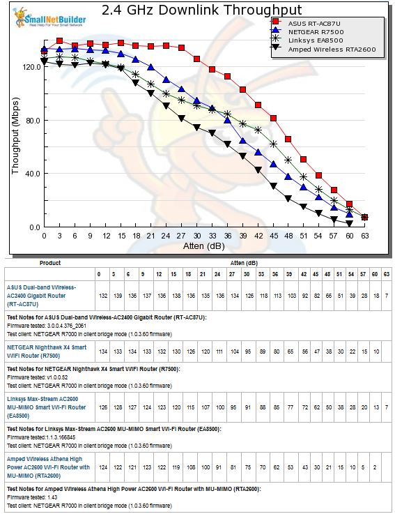
2.4 GHz Downlink Throughput vs. Attenuation
2.4 GHz uplink is a closer race. Although the Athena starts out with the highest throughput, it again starts falling off first, ending up tracking under the other three products for most of the tested range. I’d say the Linksys and ASUS are about tied for this benchmark.
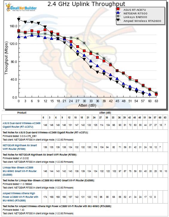
2.4 GHz Uplink Throughput vs. Attenuation
The 5 GHz downlink benchmark shows very disappointing results for the Amped Athena. It not only starts off with lowest peak throughput, but also disconnects earlier than the other three products. This result was so different, I ran extra sets of tests and even temporarily swapped in another R7000 and reran the Linksys EA8500 to make sure something wasn’t wrong with my test setup. The results were basically the same as those shown here.
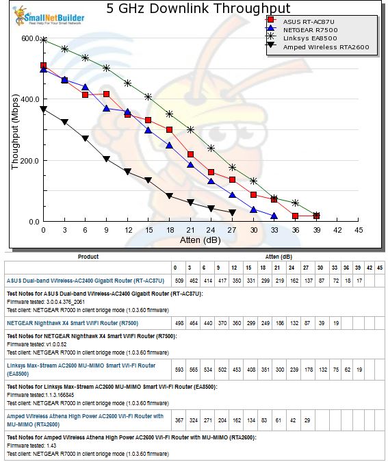
5 GHz Downlink Throughput vs. Attenuation
5 GHz uplink clearly shows the Linksys as the best of this bunch. The Amped again disappoints, disconnecting the earliest at only 30 dB of attenuation.
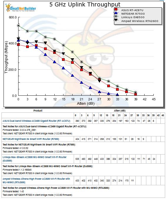
5 GHz Uplink Throughput vs. Attenuation
The take away for wireless performance is that the Athena does ok for 2.4 GHz, but once again is unlikely to live up to Amped’s superior coverage claims. But for 5 GHz, I expect coverage to be inferior to other products you can buy for much less.
Four Stream Performance
As noted earlier, I continue to use an AC1900 class STA for the performance data entered into the charts. But if you’re willing to spring for a pair of Athenas, can you expect knock-your-socks off throughput?
I set two RTA2600’s up in open air, six feet apart, one as a normal router and the other in wireless bridge mode (found in the Network Settings > Bridge Mode menu. The in-house 5 GHz network was not shut off for the test, but was idle and only beaconing (no traffic). Channel was set to 153, bandwidth mode was in its default 80 MHz mode and everything else was set to defaults, including MU-MIMO enabled. However, given the 4×4 to 4×4 nature of the link, MU-MIMO doesn’t come into play.
I connected only one computer via Gigabit Ethernet at each end of the bridge. Baseline tests using Ethernet between the two computers and TP-LINK NICs show the Ethernet link capable of a bit over 900 Mbps in both directions with each direction run separately. So the hardwired part of the link shouldn’t be a limiting factor.
I couldn’t monitor link rates for these tests, since the router’s admin GUI doesn’t show them.
The simultaneous up and downlink test yielded 815 Mbps total throughput, with an almost 3-to-1 difference between down and uplink throughput. The Linksys EA8500 yielded 830 Mbps for this test, with more battling between up and downlink.
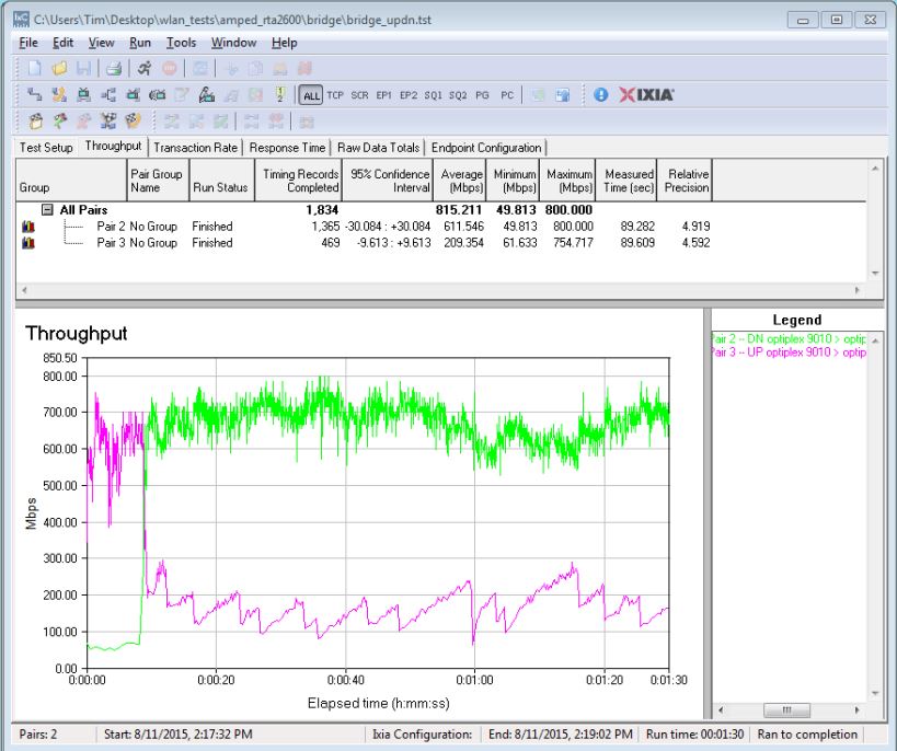
Amped RTA2600 four stream throughput – simultaneous up/downlink
Separate up and downlink tests that yielded 714 and 678 Mbps vs. 727 Mbps downlink and 667 Mbps for the EA8500.
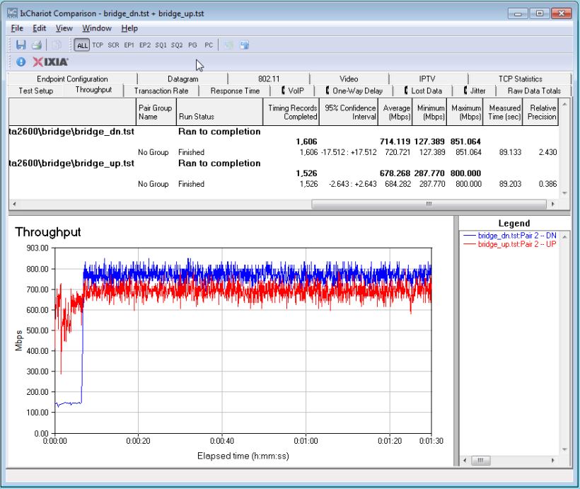
Amped RTA2600 four stream throughput – up and downlink
I also added a second pair of clients plugged into the router and bridge to see if a second stream would yield higher throughput and to ensure that the single Gigabit Ethernet connection was not limiting results. The plot shows a total 907 Mbps throughput, with one of the downlink connections getting only 15 Mbps of throughput. The EA8500 produced 924 Mbps of total throughput for its test.
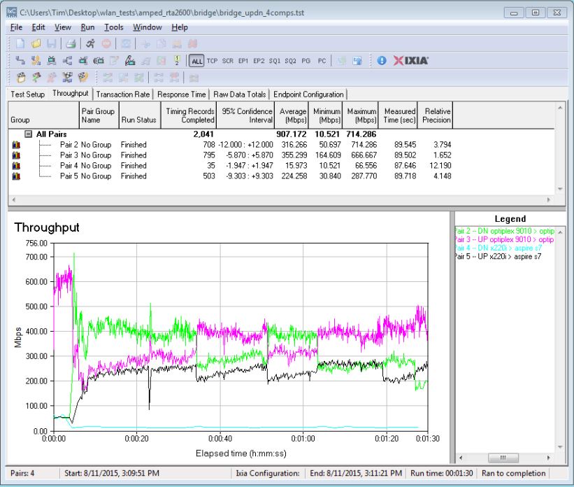
Amped RTA2600 four stream throughput – simultaneous up/downlink, angled antennas, four computers
MU-MIMO Performance
Since MU-MIMO testing requires multiple clients, our evolving test process uses open-air testing. Amped sent along Qualcomm’s reviewer’s guide, which did not suggest physical placement of the three Xiaomi Mi Note Pro smartphones supplied as MU-MIMO test devices. Don’t go looking for these in stores; they’re China only products.![]()

Xiomi Mi Note Pro MU-MIMO enabled smartphone
Smartphones: Xiaomi Mi Note Pro, Xiaomi Mi 4i, HTC One M8s, ZTE Nubia Z9 Mini, ZTE Nubia Z9 Max, LeMax and LePro1, Sharp Aquos ZETA SH-03G, Fujitsu Arrows NX F-04G
Computers: Acer Aspire E Series (14”/15), Samsung NT500R5H-K28 (15.6”)
As explained earlier, MU-MIMO’s claim to fame is improved bandwidth utilization by effectively splitting a single 4×4 radio into three 1×1’s. So the test is pretty simple:
- Disable MU-MIMO, connect three 1×1 clients, run a test to all three clients simultaneously, record each client throughput and calculate total throughput
- Repeate the test with MU-MIMO enabled
- Calculate the throughput differences
Even though I’m using different MU-MIMO test devices, I decided to use the same test conditions applied to the Linksys EA8500. I started with a "triangle" arrangement, with at least 6 feet between the Athena and each phone. The reason for this arrangement is to maximize the router’s ability to get optimum beamforming for each client by maximizing client-to-client distance at short range. Simply put, the better the beamforming, the better throughput to each client can be optimized.
All tests used the IxChariot throughput.scr script with the test file size set to 5,000,000 Bytes, TCP/IP protocol, one connection per client, 90 second test length. Each test was run once. The in-house 5 GHz network was not shut off during the test, but it was idle and only beaconing (no traffic). Channel was set to 153, bandwidth mode was in its default 80 MHz mode and everything else was set to defaults.
In the sections to follow, all plots show downlink throughput only, since that is the only direction that MU-MIMO works in. Just to be sure, I ran a few uplink tests and saw no significant throughput gain with MU-MIMO enabled.
Triangle
The first test used the triangle configuration. Due to test space limitations, I had to position one client in front, one in back and one on the right side (facing router front). All were about 6 feet from the router. This accomplished the same goal of optimizing beamforming as an equilateral triangle configuration.
The chart below shows throughput difference between MU-MIMO disabled and enabled for each client and for all three total. Throughput change for each client varied greatly from -31% worst case to 87% best. In all, this test configuration showed a total throughput gain from MU-MIMO of only 9%.
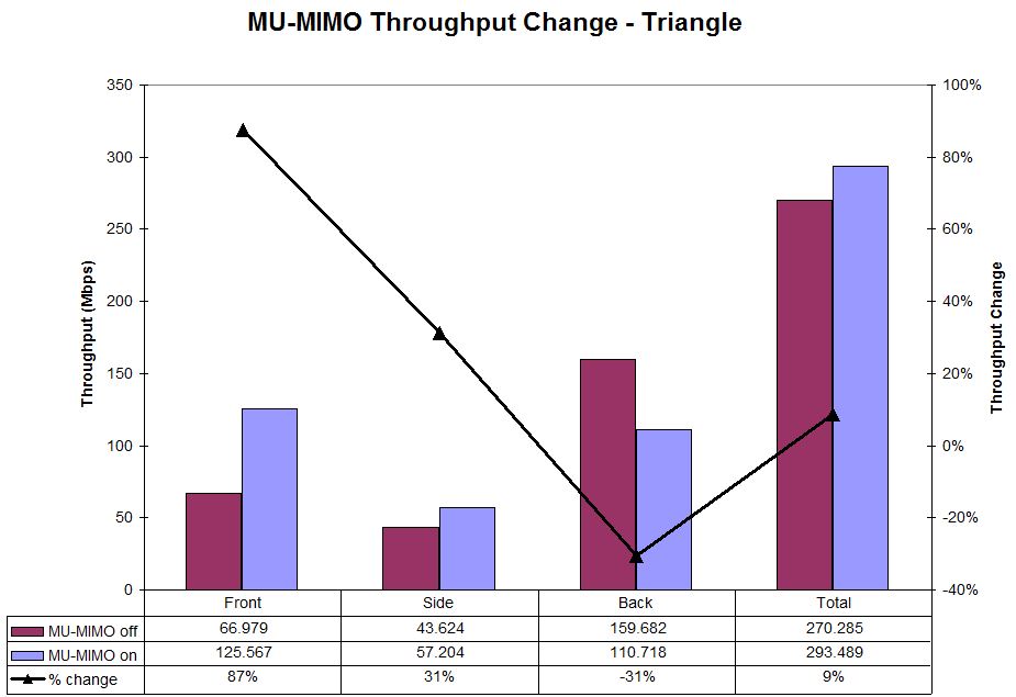
MU-MIMO Throughput change – Triangle
The IxChariot plot below shows the test run throughput plot with MU-MIMO disabled. (Note the All Pairs value in the IxChariot plots will not equal the total values shown in the throughput change charts due to the way IxChariot calculates the average throughput of a group of tests. I use the individual test average values for my throughput difference calculations.)
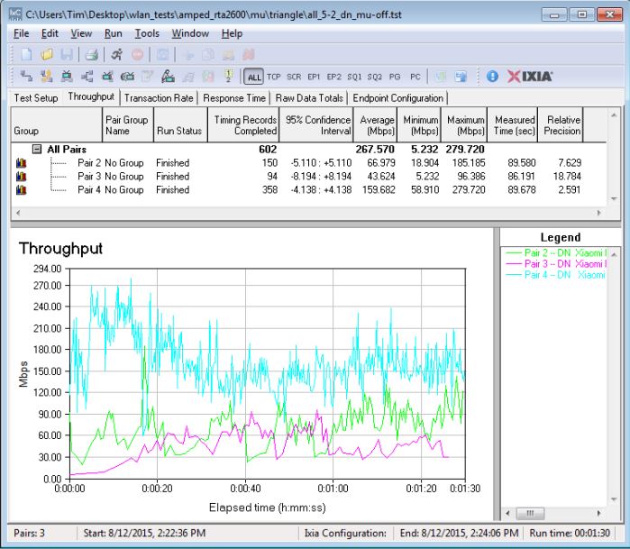
MU-MIMO Throughput – Triangle configuration – MU-MIMO disabled
And with MU-MIMO enabled.
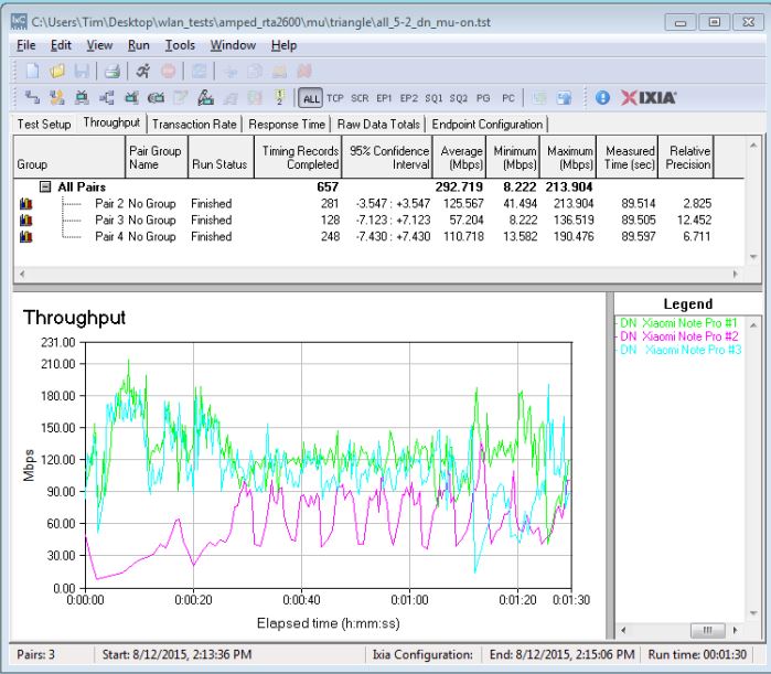
MU-MIMO Throughput – Triangle configuration – MU-MIMO enabled
This plot doesn’t have the nice uniform throughput found when testing the Linksys EA8500, as shown below. Since both router and test clients are different, I can’t really say why this is.
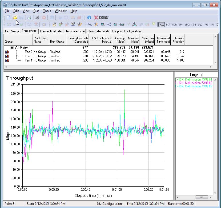
MU-MIMO Throughput – Triangle configuration – MU-MIMO enabled – Linksys EA8500
All Front
The "All Front" test is meant to be a MU-MIMO torture test because it minimizes client-to-client distance. When clients are close together, it should be more difficult to optimize beamforming for each client.
The test positions all three devices on a rack in front of the router about 6 feet away. Oddly, total throughput gain of 18% is twice the value obtained in the "optimal" triangle test. Once again, throughput and throughput change vary greatly from device to device.
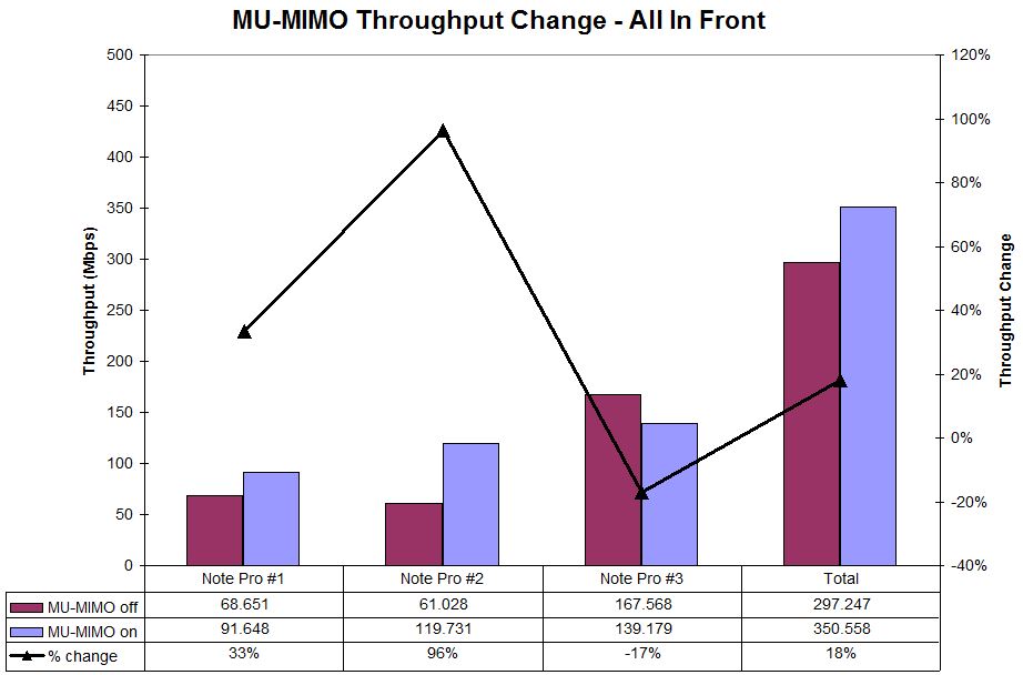
MU-MIMO Throughput change – All Front
Three Room
The last test looks at how MU-MIMO might work in a more real-world home situation with devices in different rooms. This test kept one phone on the rack in the same room as the EA8500, the second phone moved to a nearby bedroom about 25 feet and a few sheetrock walls away and the third located on a table at the far end of the hall. These locations differ slightly from those used to test the EA8500 because the Xiomi phones didn’t seem to have the range the Dell laptops had.
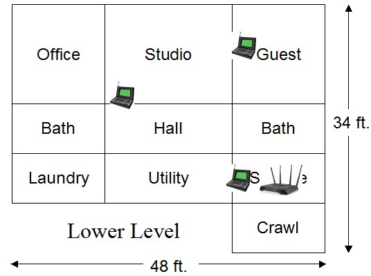
MU-MIMO 3 Room test floorplan
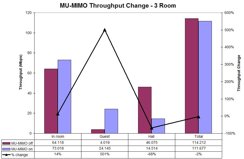
The results are interesting. Overall, the -2% throughput change is essentially a wash. But note two of the three locations had throughput gains of 68% and 501%. Of these two, the Guest room improvement is the most puzzling. Qualcomm has told me that MU-MIMO devices will switch to SU mode when signal levels drop to levels where good beamforming can’t be done. Since the Guest location had the lowest throughput, I would guess it was operating in SU (Single User aka plain ol’ Wi-Fi) mode. Yet, it showed the highest throughput gain.
Since total throughput didn’t change and since the In Room device’s throughput went up, the Guest room device’s additional throughput must have been redistributed from the Hall device. This seems to demonstrate one of MU-MIMO’s features; that it can improve throughput for even non MU-MIMO devices by using airtime more efficiently with MU-MIMO enabled devices. For this to be true, however, the In Room and Hall devices would both have to be using MU-MIMO. Since I have no way of knowing this for sure, all the above is conjecture.
MU-MIMO Throughput change – 3 Room B
More Connections Per Client
Qualcomm has been bugging me to retest the EA8500 using multiple connections per client. They assert that a single connection per client can’t fully use the available bandwith, so the MU-MIMO throughput changes shown in the review were too low. They also suggested changing the TCP/IP window size to 3 MB and using 5 connections per client.
I didn’t mess with window size, but reran the three test scenarios with three connections per client. I would have used more, but the IxChariot license generously provided by Ixia is limited to 10 total connections.
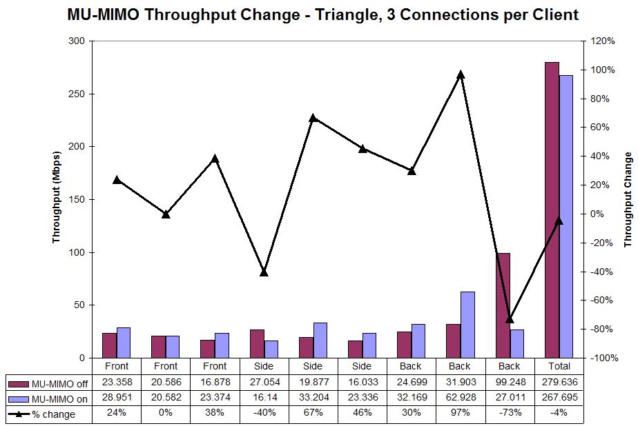
The triangle configuration, which should show the best improvement, essentially broke even with -4% change. Note, however, that some individual positions and connections did post appreciable throughput improvement—as high as 97%!
MU-MIMO Throughput change – Triangle – 3 connections / client
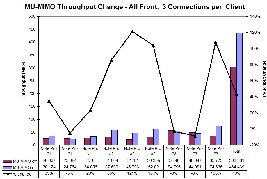
The "torture test" All Front configuration once again turned in the best total throughput improvement with 43% improvement vs. 18% with one connection per client, an almost 2.5X improvement. I don’t know why the #2 device had the best throughput gains, but it sure did!
MU-MIMO Throughput change – All Front – 3 connections / client
Finally, the three room test had 10% lower total throughput. It also once again produced the highest percentage gains with the Guest room client, which was probably in SU mode.
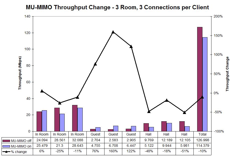
MU-MIMO Throughput change – 3 room – 3 connections / client
So it looks like Qualcomm was right, that it takes more than one connection to get the most out of a MU connection. So when does this happen in real life? Actually quite often, when your web browser launches a lot of simultaneous connections in its effort to quickly render a page.![]()
AirTime Allocation
Finally, here’s the look I promised at Athena’s Airtime Allocation feature. Airtime Allocation or Fairness is an attempt to improve wireless bandwidth allocation. Wireless routers and access points generally use the Packet Fairness method, which sends a fixed number of packets to each client. This is great when all clients are operating at the same transmit link rate, which is rare. Even in a network with all AC580 (1×1) clients, for example, clients can be operating at very different rates depending on received signal level.
Since it takes a lot longer to send the same number of packets to a client linked at 54 Mbps vs. one linked at 433 Mbps, the slower client takes up a disproportionate amount of airtime, which can affect the faster client.
Airtime Fairness allocates equal airtime to each client vs. equal packets. This lets fast clients make the most of their airtime, sending more packets when their timeslot comes up. The diagram below illustrates the two methods.
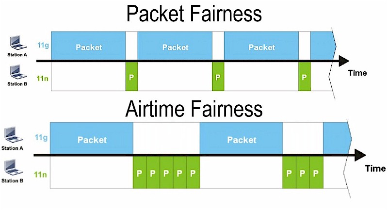
Packet vs. Airtime Fairness
Image credit: Draytek
The Athena is the first router I’ve encountered that lets you manage airtime via specific allocations. So let’s see if it works. I used two laptops:
- Slow client – Acer Aspire S7 Ultrabook running Windows 8 with an Intel Dual Band Wireless N 7260 Plus Bluetooth N600 adapter
- Fast client – Lenovo x220i running Windows 7 with a NETGEAR A6200 AC1200 adapter
I positioned the Lenovo right beside the Athena so that it reported its maximum 867 Mbps link rate. I moved the Acer to an adjacent room, which reduced its link rate to typically 243 Mbps. Both were connected to the 5 GHz band. I used the Connected Device method, which allocates airtime by device MAC address.
Let’s start with Airtime Allocation off. The IxChariot plot shows just about equal throughput, despite the more than 3X difference in transmit rates. These will be our baselines for comparison.
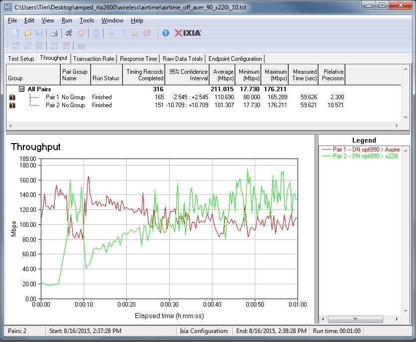
Airtime Allocation throughput – Off
Let’s first see what happens when the slower client (Aspire 7) gets 80% of the airtime and the faster (x220i) gets 20%. (Airtime Allocations must always total 100%.)
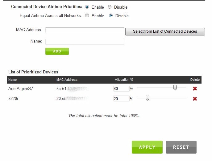
Airtime Allocation throughput – Off
The slower Acer’s throughput improves by 10 Mbps from 111 to 121 Mbps. But the faster Lenovo’s throughput drops almost 30 Mbps to 70 Mbps from 101 Mbps!
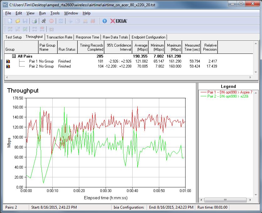
Airtime Allocation throughput – 80% to slower STA, 20% to faster
If we reverse the allocations and give the faster client 80% of airtime and the slower client only 20%, the faster Lenovo gets a throughput boost of almost 90 Mbps (101 to 190 Mbps), while the slower Acer is knocked down almost 80 Mbps (111 to 34 Mbps).
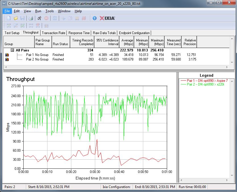
Airtime Allocation throughput – 20% to slower STA, 80% to faster
So it appears Amped has implemented an interesting bandwidth management tool in Airtime Allocation. But properly setting it may be a challenge because WLAN transmit rates constantly change. I suspect the SSID based priority method that allocates airtime among the main and four guest SSIDs per radio might be a more practical way to manage airtime in real networks.
Closing Thoughts
Once again, router makers are pushing another wave of routers to market that won’t benefit most Wi-Fi users. You need at least two MU-MIMO devices to reap the improved total wireless bandwidth yield of a MU-MIMO router and you’re not going to have any of those anytime soon.
That aside, Amped’s RTA2600 Athena has other reasons to not buy it, namely sub-par 5 GHz performance and bottom-of-the-charts storage performance. If you must have a MU-MIMO router now, Linksys’ EA8500 is a better performer, and about $40 cheaper, too.
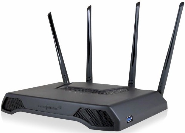 Buy Athena High Power AC2600 Wi-Fi Router with MU-MIMO from Amazon
