Introduction
In the last installment, I described the general approach to the project, my home’s layout and how I generated my “drop list”. This time I’m going to cover the design and material selection for the wall plates and central wiring panel.
But first, I need to step back a bit to respond to this reader’s question, which I had intended to cover in Part 1, but frankly, forgot to!
“I was excited about the article, but then heavily disappointed to learn the networking was all wired. What about some pre-802.11n wireless network that links up all the mentioned devices and rooms without the neccessity of demolishing the walls, having cables all around the house etc.”
The simple answer is that wireless is not ready for prime time as the sole medium for building a home network. While the range vs. throughput performance of the MIMO wireless products that I’ve seen that are based on Airgo’s TrueMIMO technology is truly impressive, there is nothing in the technology that specifically addresses QoS issues required for handling real-time applications such as VoIP and especially high-definition video streams.
In addition, manufacturers insist on promoting products that use the overcrowded 2.4GHz spectrum. Interference from other products in this band has a high probability of at best degrading network throughput, and at worst, shutting down a network entirely. This isn’t to say that wireless technology capable of handling most home networking needs won’t come along at some point in the future. But if you’re building a network today, you still need cables to support “mission critical” (must-have) applications. Now back to the story…
Now that I knew what I wanted to run, I had to figure out where. Since I used the “home run” wiring method, each cable would run from a central location to wall plates in the rooms. Because my Utility room is centrally located on the lower level, it was a natural spot to locate my wiring panel. All I had to do was pick a spot that was out of the way of the HVAC unit, water pump and water heater that also had to occupy that room and make sure a power outlet was installed nearby to power the networking gear.
Figure 1 shows all the drops that I had my electrician run. He charged $50 per drop which I judged to be worth it, since I didn’t have to coordinate with any of the subcontractors’ schedules, nor did I have to drill the holes, pull the cables, mount the boxes, etc.

Figure 1: Drops waiting for the central panels
(click image to enlarge)
Since I wasn’t planning on installing any especially power-hungry gear near the network panel, I had the electrician also run a single 20A circuit to a single duplex outlet (that’s the yellow cable in Figure 1). I didn’t bother putting in any more outlets, since everything was going to be plugged into a couple of UPSes anyway. I did have the electrician, however, connect the circuit to my home’s distribution panel that can be cut over to an emergency generator. That way, I can still have Internet access if main power fails.
On to the wall plates!
Wall Plates
I decided to use simple wall plates (Figure 2) that mount directly to standard electrical wall boxes instead of the “Decora” style (Figure 3) that has separate insert and wall plates because the simple plates are less expensive and work just as well. I got my plates, and most of the other supplies that I used from Deep Surplus. (While Deep Surplus has been an ongoing advertiser, I got my stuff the same way you would… I paid for it!)
 |
 |
| Figure 2: Standard Wall Plate |
Figure 3: “Decora” Insert Plate |
| (images courtesy of Deep Surplus) | |
The plates take standard “keystone” style inserts, which hold the actual connector and snap into the cutouts in the plates. Figure 4 shows the two inserts that made up my wall plates – a CAT5e jack on the top and “F” style coax connector on the bottom.

Figure 4: CAT5e and F connector keystone inserts
(images courtesy of Deep Surplus)
TIP: Many manufacturers, including Leviton, AMP, Siemon and Pass & Seymour/Legrand make modular plate / insert systems, but they aren’t all physically compatible with each other. Fortunately, I found that the plates and inserts I purchased from Deep Surplus were compatible with those from Leviton. This came in handy when I ran out of something, because I was able to pick up the Leviton equivalents at HomeDepot.
Even though plates are available that take up to six connector inserts, I took my electrician’s advice and used a maximum of three cables per electrical box. You can actually deal with the stiffness of more than three CAT 5 cables when terminating cables and stuffing the cables back into the box when you attach the plate to the wall box. But I found wrestling with three RG 6 coax to be plenty challenging when trying to get the plate screwed down onto the box.
I ended up using mostly three position wall plates, but also had some two position plates. Most of the three position plates looked like Figure 5 when completed with data, phone and video jacks, while others held three F coax connectors, and one carried three CAT5e connectors for the two data and one phone line to my office.

Figure 5: Plate with data, phone and video jacks
You’ll note that I used CAT5e connectors for both data and phone, with the only difference being the color of the jack. The 4 position RJ11 plug used by most consumer phone equipment fits nicely into the 8 position RJ45 jack, as does the 6 position RJ12 connector used by some telephone equipment.
Data and Phone Patch Panels
Ever wonder why Ethernet cables and connectors are wired the way they are? Turns out it’s not just to make them more difficult to terminate, but to be backward compatible with phone wiring conventions. The EIA / TIA T568 A/B standard was designed so that one wiring pattern could be used to handle telephone, ISDN and data applications.
The “pair” numbers in Figure 6 refer to the different colored twisted pairs of wires in an eight conductor CAT5 cable, with each “pair” carrying a single phone line.

Figure 6: T-568 A/B pinouts and pairs
(image courtesy of A.P.T. Communications)
(click image to enlarge)
Note that since pair #1 ends up on the two center contacts (4 and 5) of the eight-conductor RJ45 jack, they will make proper connection to a phone’s 4-conductor RJ11 plug. Note that the lower T-568A pinout puts the second wire pair on contacts 3 and 6 of the jack for proper connection to a two-line telephone. This is why most wiring guides recommend its use instead of the alternative T-568B pinout. Since Ethernet relies on just the orange and green pairs (pins 1, 2 and 3, 6) being connected and doesn’t care which is which, it doesn’t matter whether T-568A or B is used for pure Ethernet applications.
With the decision of T-568A / B out of the way, I next had to decide how I was going to terminate all the CAT5e at the wiring panel. The cheapest way to go was to not use a patch panel at all, but instead just crimp an RJ45 plug onto the end of each cable. After all, the data lines will just end up getting plugged into a switch port, so why have the extra layer of interconnect? I almost went this way, but remembered how much I hate getting the wires lined up properly to crimp into an RJ45 plug. So despite the added cost, I decided to use a patch panel.
The question I next had to face was whether to use a patch panel with RJ45 jacks (Figure 7), telephone style “punch down” panel (Figure 8), or one of each for data and phone drops respectively.

Figure 7: CAT5e patch panel
(images courtesy of Deep Surplus)

Figure 8: 110 block with terminated cables
(click image to enlarge)
(image courtesy of Leviton Voice & Data Division)
Data and Phone Patch Panels – more
While researching these alternatives, I found that punch-down “connection systems” are available (such as Siemon’s S210) that are rated for up to CAT6 termination! This meant that I could use either flavor of patch panel for both data and phone drops.
In the end, however, I opted for using two 12-position CAT5e RJ45-style panels for both data and phone drops, with three things influencing my decision. The first was that I would have ended up having to make jumper cables to go from the punch-down block to RJ45 plugs for any of my data connections. (I could have purchased these cables, but the cost was prohibitive.)
The second reason was that punchdown blocks are more intended for terminating large multi-line trunk cables so that they can be cross-connected to individual phone jacks instead of connecting multiple phones to a single telco line. While techniques exist for connecting multiple drops to a single phone line, they’re not really recommended.
In the end, the thing that tipped the scales toward using RJ45-style patch panels was my discovery of Leviton’s 47609-EMP Telephone Patching Expansion Board (Figure 9). While it was a bit pricey at around $26 at SmartHomeUSA.com, it did the trick for me, with the ability to connect up to seven phone drops to up to four telco lines.
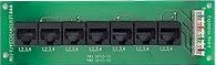
Figure 9: Leviton Telephone Patching Expansion Board
Although seven drops was not enough to support all of my planned phone jacks, it was fine to at least get me started. And I could always use just plain ol’ phone jack-splitters in a pinch if I ran out of jacks on the board.
Coax Patch Panel
With the CAT5e patch panel decision out of the way, the next task was to figure out what to do about coax cable termination. I looked at a variety of packaged solutions, but most were oriented around passive splitters and / or video distribution amplifiers, which didn’t really fit my needs. My video distribution is a work in progress, with one or two DirecTV DVR’s eventually involved. My main requirement was to be able to route one or two lines from the dish LNB to the desired coax jacks – distribution of the analog video out from the DVR was secondary.
These requirements turned me toward looking at simple coax patch bays, where I found some pretty high prices. The best deal I found was a Signamax 12F-FT 12-Port F Type Connector Feed-thru Patch Panel at Data & Telephone Supply for about $27. The design of this panel seems to have changed from when I ordered it and now comes with a wall-mount panel. But what I received was just a straight panel suitable for mounting in a 19 inch rack and didn’t really fit into the space I had allowed for my central patch panels.
So I ended up returning it and made my own panel out of plastic duplex wall boxes, wall plates and F connector inserts as shown in Figures 10 – 12. While this took more effort than buying a blank panel and stuffing F connector inserts into it, there was something about paying $13 (and up) for a blank panel that just didn’t sit right with me.
 and unmodified plastic duplex wall box")
Figure 10: Modified (left) and unmodified plastic duplex wall box
(click image to enlarge)
The box “modification” consisted of taking a keyhole saw with a metal / plastic blade and removing as much of the back of the box as I could while still giving me a strip of material to screw the box to the wall. The additional open space let the cables flex as needed when the time came to secure the wall plates with mounted coaxes to the modified wall boxes. You can see I was even able to get a plate with six coaxes successfully done, which would not have been possible had I not modified the boxes.
 Figure 11: Modified boxes mounted (click image to enlarge) |
 Figure 12: Finished Coax patch panel |
That about wraps it up for now. Next time in Part 3, I’ll cover what I learned about connector termination and some thoughts on how everything turned out.