Introduction
For wireless products tested after July 24, 2011, see this article.
For wireless products tested between June 19, 2008 and July 23 2011, see this article.
For wireless products tested after November 2005 to before March 2007, see this article.
For wireless products tested after October 1, 2003 to before November 2005, see this article.
For wireless products tested before October 1, 2003, see this article.
Wireless LAN product testing has always been plagued by the inability to perform repeatable, consistent testing among products. This is primarily caused by the lack of consistent test environments that are free of RF interference.
While we’re fortunate at SmallNetBuilder to have a quiet RF environment, we have used the same walk-around test method used by most every other reviewer. We haven’t bothered to use the rotating table that some publications use to achieve more "consistent" results because, with so many other uncontrolled factors, we didn’t think the effort produced results any more useful than our stationary client method.
On the plus side, however, through the continuing generosity of first NetIQ and now Ixia, we have been able to use IxChariot for our throughput measurements. This has allowed us to present detailed measurements and analysis unmatched by other publications for not only wireless products, but routers and other networking products as well.
Now through the generosity of another company, we are able to once more raise the standard for wireless product reviews.
New Range Test Method
Starting in March 2007 with the review of the draft 11n Buffalo nFiniti Dual-Band router, we switched over to using Azimuth‘s ACE 400NB Channel Emulator, Director and Radio Proof™ enclosures for wireless LAN product range testing. The Azimuth system provides a controlled, interference-free RF environment with programmable attenuation that can be used to repeatably simulate varying distance between AP (access point or wireless router) and STA (client) devices. This allows us to present a complete throughput vs. range profile for devices over their entire operating range.
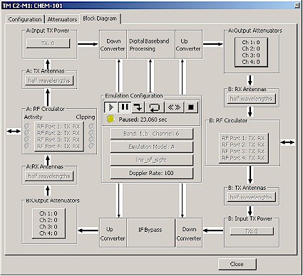
The ACE is internally a very complex box, performing bi-directional emulation of up to 32-channel 4×4 MIMO systems. You can choose from six standard usage models as well as two special modes: Bypass and Butler. Figure 1 shows a block diagram of the ACE, so that you can get an idea of what’s inside.
Figure 1 : Azimuth ACE NB Block Diagram
We can’t begin to scratch the surface of what the ACE can do and how it does it, but the basic idea is that the ACE digitizes the incoming signal from up to four channels and applies some pretty hefty digital signal processing to it to simulate multipath, delay, fading and the other stuff that happens to the RF signals in the real world. After all the crunching, the signal is converted back to analog and sent out the second set of ports.
Throughput vs. Path Loss
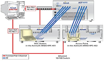
Figure 2 shows the Azimuth ACE test setup for testing throughput vs. signal level. But since the Azimuth system can control only the loss or signal attenuation between AP and STA and not the signal level directly, this test is more correctly called Throughput vs. Path Loss.
Note that direct connection is made to the antenna connectors for both AP (access points and wireless routers) and STA (client) devices. This is required so that the ACE can be in total control of what happens to the signals between AP and STA.

Figure 2: Azimuth ACE Test Setup
For APs without removable antennas, we remove all or part of the AP enclosure. Since most STAs don’t have external antenna connectors, we do what’s needed to get at the miniature antenna connectors that are now found on most STA devices. This usually involves cutting away part of the plastic housing of the CardBus cards that we usually receive for testing with APs.
APs are then placed into one of Azimuth’s RF-tight enclosures and connected to the ACE. The STA card is inserted into a 1.2 GHz Pentium M notebook running WinXP Pro and Azimuth software that enables communication between the Azimuth system and the STA under test, which is placed in another Azimuth "Radio Proof" enclosure and also connected to the ACE.
We then perform a complete Throughput vs. Path Loss test in 3dB increments starting at a level of -55 dBm down to where the product loses connection. The ACE is set to use its Butler emulation mode. According to this article,
a Bulter matrix is commonly used to provide a static emulation of a real environment to evaluate multi-signal/multipath transmission. A Butler Matrix consists of some Hybrids, some Phase shifters and some cross couplers, with multiple inputs and multiple outputs.
An Azimuth application note adds:
When this mode is selected, the channel is configured to have a unity gain, non-fading channel with channel (phase) matrix (Figure 3). Generically, the Butler mode provides a channel with a high degree of linear independence.

Figure 3: Butler matrix phase conditions
For our purposes, the key thing to know about the Butler matrix is that it presents a best-case condition for throughput measurement.
Traffic generation and measurement for the test is done by IxChariot, running the throughput.scr script using TCP/IP. The only modification we make to the script is to adjust the file size from its default of 100,000 Bytes. We typically use 300,000 Bytes for 802.11g products and 3,000,000 Bytes for draft 802.11n.
The products under test are run with their default settings unless otherwise noted, to emulate the "out of the box" performance that buyers will experience.
The script is usually run for 30 seconds at each programmed attenuation, with a 5 second pause between tests.We record the average throughput reported by IxChariot at each signal level. We test both uplink and downlink profiles in separate runs.
Using the Curves
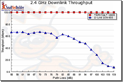
The result is a complete throughput profile of the AP and STA pair over its entire signal operating range. Figure 4 shows sample downlink test results for a D-Link DIR-655 and DWA-652, plotted along with an 100 Mbps Ethernet line for reference.

Figure 4: Throughput vs. path loss test results
Note that the X axis in Figure 4 is Path Loss (or signal attenuation between AP and STA) in dB, not distance. Because there is no fixed relationship between Path Loss and distance due to the varying attenuation characteristics of real-world environments, these results can only be used comparatively. In other words, while they won’t tell you exactly how far you can expect a product to operate, you will be able to use the results to compare the relative performance of products.
How you use the curves to select products depends on the performance that you are looking for. But here are some general guidelines:
- The further out that the curve’s "waterfall" portion is (that’s the part where throughput starts to fall off), the better. This means that throughput will remain higher for longer distances.
- The steeper the slope of the "waterfall", the quicker a product will lose connection as you move out of range.
- Products that operate at path losses of 100+ dB are not necessarily better. 5 Mbps might be fine for web surfing and checking email, but no good for video streaming or large file transfers.
Other Tests
Since we have a quiet RF environment, other wireless testing is conducted in free air using the antennas supplied with the products. Tests are run with the IxChariot throughput.scr script and the products in their default settings unless otherwise noted.
Other tests include:
Maximum throughput – We run a maximum throughput test for 1 minute with devices approximately 3 to 10 feet apart. This serves as a "sanity check" on the Azimuth results and is the throughput plot typically shown in most reviews.
Security mode throughput – We set AP and STA to any of the following security modes that are supported—WEP 128, WPA-PSK / TKIP and WPA2 / AES—and run a throughput test for 1 minute.
Other testing is performed as needed, including throughput with mixed clients and neighboring WLAN interaction testing. These tests are described in the reviews in which they are run.
If you have comments or questions about these test methods, please post a comment below or contact us.

