Introduction
![]() NOTE:This article describes the wireless test procedure for products tested after May 15, 2017. The previous Revision 9 process is described here.
NOTE:This article describes the wireless test procedure for products tested after May 15, 2017. The previous Revision 9 process is described here.
The key changes in the Revision 10 process are:
- New test client devices that support up to 4×4 operation, 256 QAM on both bands and 80+80 / 160 MHz bandwidth
- Switch from IxChariot to iperf3
- Shorter test time
- Elimination of simultaneous up / downlink test
Refer to How We Test: SmallNetBuilder’s Wireless Testbed – Revision 10 for testbed construction details.
Throughput vs. Attenuation Test Configuration
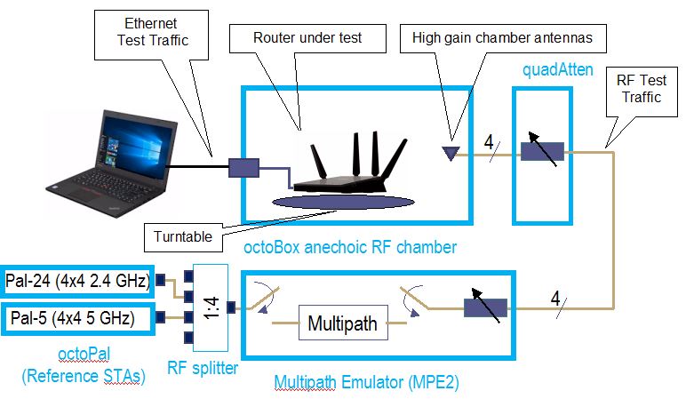
The throughput vs. attenuation test configuration is shown below. All RF connections contain four separate signal paths.

Revision 10 configuration – Throughput vs. attenuation
We continue to use 20 MHz bandwidth in 2.4 GHz for throughput vs. attenuation testing. This is what most devices will use, given mandatory 40 MHz coexistence mechanisms and overcrowded 2.4 GHz band. However, in recognition that 256 QAM in 2.4 GHz has become a de facto standard for 802.11ac client devices, our octoScope Pal test client now uses 256 QAM in both 2.4 and 5 GHz. This results in a maximum 2.4 GHz link rate of 192 Mbps (20 MHz bandwidth) and 867 Mbps in 5 GHz (80 MHz bandwidth) for the 2×2 configuration that remains our standard for throughput vs. attenuation testing.
All wireless router performance testing is done on the LAN side of a router under test so that the product’s routing performance does not affect wireless performance results, i.e. the Ethernet client is connected to a router LAN port. Access points are tested using their Ethernet port.
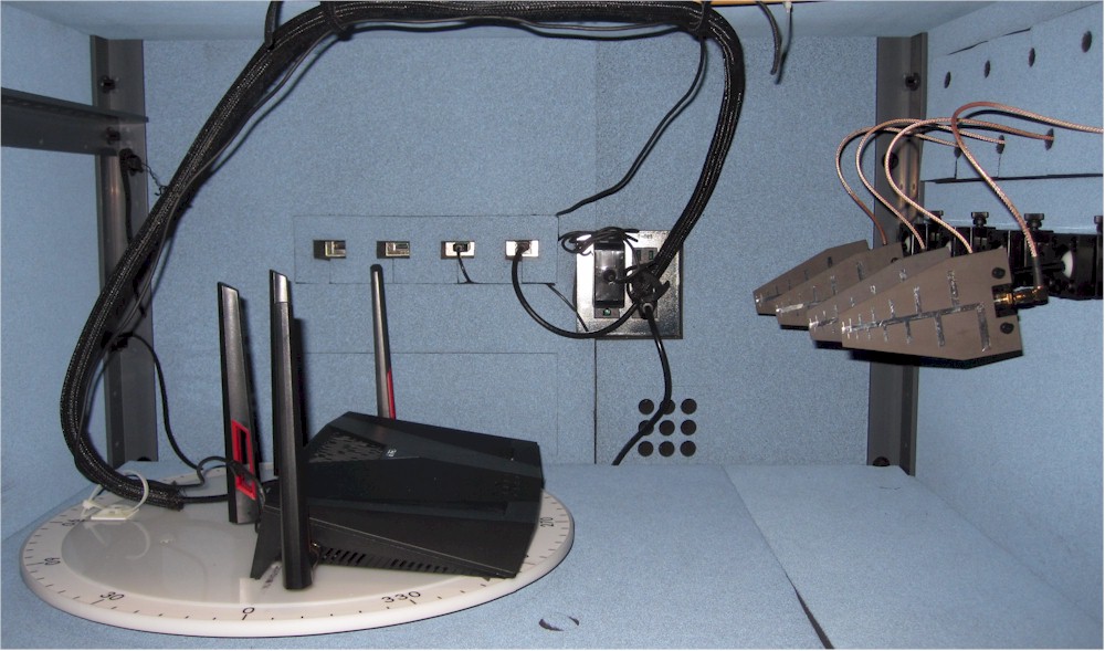
The wireless router / AP under test (DUT) is centered on the upper test chamber turntable in both X and Y axes. If the DUT has external antennas, they are centered on the turntable. If the antennas are internal, the router body is centered. Distance from center of turntable to chamber antennas is approximately 18 inches (45.72 cm).
Initial orientation (0°) is with the DUT front facing the chamber antennas. The photo below shows the 0° starting position for an ASUS RT-AC88U router.

ASUS RT-AC88U in Upper Test Chamber – "0 degree" Position
The router or AP under test is prepared as follows:
- Check / update latest firmware
- Reset router to defaults
- Change router settings:
- LAN IP: 192.168.1.1
- 2.4 GHz: Channel 6, Bandwidth: 20 MHz, Security: WPA2 / AES, Key: 11111111
- 5 GHz: Channel 40, Bandwidth: Auto or 80 MHz, Security: WPA2 / AES, Key: 11111111
Throughput vs. Attenuation Test Process
Note: "Downlink" means data flows from router to client device. "Uplink" means data flows from client device to router.
The general test process is as follows:
- Associate Pal client device, either 2.4 GHz or 5 GHz. Record connection link rate.
- Run iperf3 manual test to check throughput
- Run test script
- Power cycle DUT and repeat test
Testing is controlled by a Tcl script supplied by octoScope for throughput testing. The script executes the following test plan:
- Move the turntable to starting position. This places the DUT at the "0 degree" starting position previously described.
- Set the attenuators to 0 dB
- Set the MPE-2 to NLOS mode (multipath inserted), attenuators = 10 dB for 2.4 GHz, 0 dB for 5 GHz.
- Set the Pal device
- For 2.4 GHz: ac mode; Channel width = 20 MHz; Primary Channel = 6; Guard Interval = Adapt, MCS = Adapt, Max MIMO Streams = 2, WMM Priority = Best Effort
- For 5 GHz: ac mode; Channel width = 80 MHz; Primary Channel = 40; Guard Interval = Adapt, MCS = Adapt, Max MIMO Streams = 2, WMM Priority = Best Effort
- Move the turntable to -180° (counter-clockwise)
- Start 40 second iperf3 test (downlink)
- Wait 10 seconds, then start turntable rotation to +180° at 2 RPM.
- Wait for test to finish
- Discard first 10 seconds of iperf3 data, calculate average of remaining data and save to CSV file.
- Repeat Steps 5 to 9 for uplink (STA to DUT)
- Increase attenuators by 3 dB.
- Repeat Steps 5 to 11 until attenuation reaches programmed attenuation limit or device disconnects. Attenuation limit is 45 dB for 5 GHz, 63 dB for 2.4 GHz.
Two test runs are made in each band for dual-band devices. The CSV files from the two test runs are merged into a single Excel file and the average of the two runs calculated. The average of the two runs is the value entered into the Charts database for the 2.4 / 5 GHz Downlink / Uplink Profile (4 benchmarks).
Throughput vs. Attenuation Test Notes
Moving the DUT through an entire 360° while the iperf3 test is running removes orientation bias from the test and eliminates the need to determine the "best" run out of multiple fixed-position tests. Because throughput typically varies during the test run, the averaged result tends to be lower than a fixed position test. Rotation at lower signal levels, particularly in 5 GHz, frequently causes the connection to be dropped sooner than if the DUT were stationary.
The 10 dB of extra attenuation in 2.4 GHz offsets gain from the high-gain antennas that produces levels that overload the Pal clients.
iperf3 does not have IxChariot’s throughput step-up at the beginning of a test run. Repeatibility studies also showed no appreciable difference between 30 and 60 second test run results. As a result test time, per attenuation setting was reduced from 90 to 40 seconds. The first 10 seconds of each run is discarded and only the last 30 seconds is averaged to yield the recorded test result.
Note that the simultaneous up and downlink throughput benchmark has been dropped from the Revision 10 process.
Peak Wireless Throughput Test Configuration
The octoScope Pal devices support up to four transmit / receive streams. They replace the VeriWave blade for peak wireless throughput tests.
We continue to use 40 MHz bandwidth mode for peak 2.4 GHz tests. As mentioned above, we are also using 256 QAM for both 2.4 GHz and 5 GHz. This yields maximum 4×4 link rates of 800 Mbps in 2.4 GHz and 1733 Mbps in 5 GHz.
The Throughput vs. Attenuation test configuration is also used for peak throughput tests.
The router or AP under test is prepared as follows:
- Check / update latest firmware
- Reset router to defaults
- Change settings:
- LAN IP: 192.168.1.1
- 2.4 GHz: Channel 6, Bandwidth: 40 MHz, Security: WPA2 / AES, Key: 11111111
- 5 GHz: Channel 40, Bandwidth: 80 MHz, Security: WPA2 / AES, Key: 11111111
Peak Wireless Throughput Test Process
The following test process is run for 2.4 and 5 GHz, uplink and downlink:
- Move the turntable to starting position. This places the DUT at the "0 degree" starting position previously described.
- Set the attenuators to 0 dB
- Set the MPE-2 to LOS mode (multipath bypassed), attenuators = 10 dB for 2.4 GHz, 0 dB for 5 GHz.
- Set the Pal device
- For 2.4 GHz: ac mode; Channel width = 40 MHz; Primary Channel = 6; Guard Interval = Short, MCS = Adapt, Max MIMO Streams = 4, WMM Priority = Best Effort
- For 5 GHz: ac mode; Channel width = 80 MHz; Primary Channel = 40; Guard Interval = Short, MCS = Adapt, Max MIMO Streams = 4, WMM Priority = Best Effort
- The Pal client is associated to the device under test
- Run 70 second iperf3 throughput test with eight simultaneous TCP/IP sessions (iperf3 parameters: -t 60 -O 10 -P 8 -l 32K -w 2M )
- Discard first 10 seconds of iperf3 data, calculate average of remaining data and save to CSV file
Each CSV file value is entered into the Charts database as Peak 2.4 / 5 GHz Downlink / Uplink (four benchmarks).![]()
