Introduction
In Part 1 of this series, I described the general approach to designing my new home’s network, and how I generated my “drop list”. Part 2 covered the design and material selection for the wall plates and central wiring panel. In this last installment, I’ll cover some tips and tricks that I learned during the wiring process and how it all turned out.
The first thing I did to start the wiring process was to organize the drops in the utility room and put up a panel where I could mount all the wiring components. You would think that I would be able to find a scrap piece of plywood amid all the construction debris, but I ended up purchasing a 2 ft. X 2 ft. pre-cut panel from my local building supplier. I secured the panel to the wall with sheetrock screws – the next best thing to duct tape – and screwed the two data patch panels, one phone patch panel and three DIY coax “patch panel” outlet boxes to it.
I next separated the tangle of cables into three bundles for the data, phone and coax patch panels, which ended up being more difficult than I had planned. The RG 6 coax was no problem, but I hadn’t been explicit enough in my instructions to the electrician for how to mark the CAT 5e cabling that was used for both phone and data drops. He ended up marking the cables with masking tape labels, most of which had fallen off by the time I got to reading them.
The lesson here is to use a cable marking system that is robust enough to withstand both the wirepulling process and the abuse the resulting pile of cables in your wiring closet will probably take from being stepped on, thrown out of the way, etc. by various construction tradespeople. In the end, writing directly on the cable with a Sharpie or other permanent marker would probably have been a better way to go.
Cabling Tips
But my other brilliant move made the missing labels moot anyway. In my rush to get everything organized for termination, I lopped 6 to 10 feet off of all the CAT 5e cables along with, yup, any labels that had survived the wire pulling and construction process. Fortunately, I had planned on needing to do some cable sorting and had ordered a cable tracing kit along with my connection supplies.
I used a B&K Model 262 (Figure 1), which includes a tone generator terminating in alligator clips and RJ11 plug and a tracer probe. I got mine for a little under $70 (including shipping) from Tequipment.net.

Figure 1: BK 262 Tone Generator & Cable Tracer Kit
While this isn’t a tool that I’ll need on an ongoing basis, it paid for itself in the time I saved sorting out the mess of cables that I created.
The other thing that was helpful in sorting cables into their proper bundles were “Velcro” cable straps and releasable cable ties. I got the cable straps from DeepSurplus and picked up the Thomas and Betts Releasable Ties from Lowe’s. I fastened 10 inch staps to the bottom of my floor joists as shown in Figure 2, using a T&B plastic tie base and a couple of sheetrock screws to form a sort of U-channel that allowed me to pull the strap back and forth as needed.

Figure 2: Releasable cable strap detail
Figure 3 shows the finished product, which holds the cable bundle neatly, but still lets me get at individual cables as needed.

Figure 3: Cable raceway w/ Velcro straps
(click image to enlarge)
Time to Terminate
Now that I had my cable bundles under control, I started the termination process. I started at the outlet boxes, and just started attaching connectors. The coax was easy, since I used screw-on type connectors (Figure 4) that didn’t require crimping. But two tools proved invaluable here: locking pliers, which allowed me to get a good grip on the connector and keep my hands from getting torn up while twisting on the connectors; and a coax stripper (Figure 5).

Figure 4: RG 6 Twist-on connector
(image courtesy of Deep Surplus)
Figure 5: Coax stripper
(image courtesy of Deep Surplus)
The locking pliers I already had and the TL252 stripper cost me only $10 from DeepSurplus. This stripper uses three blades and strips the outer jacket, shield braid and inner insulator at the same time, turning a chore that normally takes me a minute or so (and a few nicked fingers) into literally a 5 second job.
Putting on the RJ45 jacks took a bit more time, but I also purchased a UTP cable stripping tool (the TL230 from Deep Surplus – about $9) that helped speed things along by letting me quickly and cleanly get the cable outer jacket stripped. The RJ45 jack terminals themselves are IDC (insulation displacement connector) type, i.e. they cut through the insulation without your having to strip it.
For some reason, I convinced myself that using a punch-down tool to terminate the RJ45 jacks was going to be a hassle, so I initially ordered “toolless” jacks. But it turned out that these jacks required me to perform a task I personally dread – sorting UTP wires into order and holding them there while performing the termination.
So I ended up returning the jacks and ordering regular punch-down type jacks. I still had to sort through the color-coded wires during termination (tough for us partly color-blind folks), but punching down the wires individually was quick and easy and, at least for me, less error-prone. Figure 6 shows one of each jack flavor – “toolless” in blue and punch-down in white.

Figure 6: “Toolless” and punch-down type RJ45 jacks
I also ordered and returned a punch-down tool and 110 style blade because the data patch panels each came with a cheap tool that worked just fine.
TIP: Some folks like to use a small-blade screwdriver to do their termination. But I wouldn’t recommend taking the risk of widening the terminals and creating an intermittent, or worse, high resistance connection that would be miserable to troubleshoot.
Patch Panel Punch-down
Once I had all the outlet boxes terminated, I turned my attention to the patch panels. This was where the cable tracing kit that I described earlier came in handy, along with a cable test kit I had purchased a few years ago (Figure 7).

Figure 7: Cable Test kit
I forget where I got mine (Figure 7 comes from Altex Computers and Electronics), but they are pretty widely available. The kit consists of the larger test box, smaller “remote”, adapter cables and carrying case. All you need to do is plug the boxes into the two ends of a cable run, turn the test box on and put it into auto (scan) mode.

Figure 8: Testin’ cables
If you’ve connected everything up correctly, the lights will march in sequence from 1 to 8; if not, you’ve got work to do.
So my patch panel punch-down sequence went something like this:
1) Walk to an outlet box and plug the cable tracer tone generator into a white (data) jack or blue (phone) jack (the built-in RJ11 cable was handy for this).
2) Walk back to the patch panel, use the cable tracer probe to find the tone, then mark the cable. ( Direct contact with the wire isn’t necessary, since the probe senses the RF field created by the tone generator.)
3) Walk back to the outlet box and remove the generator so that I don’t accidently short it while cutting and terminating the cable on the other end. (The tone generator might have had output protection built-in, but I wasn’t going to risk it.)
4) Walk back to the panel, complete the punchdown, and plug in the cable tester.
5) Walk back to the outlet, plug in the cable tester remote and cross my fingers.
6) Rinse and repeat
You can see I would have saved a lot of hassle (and walking) by not screwing up on the cable marking!
Coax Panels & Outside Runs
Terminating the coax patch panels was easy in comparison to the data and phone panels because I didn’t need to have the coaxes grouped in any particular way. The main issue here was dealing with the stiffness of four to six RG 6 coaxes when it came time to screw the plate down to the outlet box. I found that having plenty of slack in the coax cables was a big help and that I was glad that I had used releasable cable ties! Figures 9 and 10 show the coax panels before and after termination.

Figure 9: Modified boxes
|
 Figure 10: Finished Coax patch panel |
With the inside work done, it was time to get my outside connections done. My electrician had also installed three CAT5e and four RG 6 runs between the patch panel drop area inside and the outside wall that had been designated for the telco demarc box and entry point for my satellite dish cables. I actually had only wanted two CAT5e cables, but figured the extra run the electrician installed by mistake would come in handy at some point.
I came out to the house one day and found that the local telco had installed service. I had intended to do the connection to the demarc box myself, but found that the installer had connected up all three CAT5e cables he found lying on the ground! No harm done here, since the cables hadn’t been connected inside, so I just left them all connected. At least this way, the ends were out of the weather and out of harm’s way of the lawn mower and curious pets.
Patching in the Phones
The telco installer had naturally followed the T-568A wiring convention, which I had also chosen, so I didn’t have to do any color code conversion when it came time to terminate one of the CAT5e cables from the demarc at the Leviton 47609-EMP Telephone Patching Expansion Board I had chosen for phone line patching.
Figure 11 shows a detail of the demarc CAT5e cable terminated to the Leviton board and also how both normal “data” patch (blue) and RJ11/RJ12 “phone” (beige) cables can be used for phone patching with this board.

Figure 11: Phone patch panel detail
(click image to enlarge)
Figure 12 is an expanded view showing the somewhat messy, but effective, system of patch cables between the Leviton board and the RJ45 patch panel that I had terminated all my “phone” runs into. I chose to install some of my DSL filters here instead of at the other end, which required the use of RJ11/12 cables for those patches. The larger beige box is a combo DSL filter / Y jack supplying an unfiltered connection to my DSL modem and filtered connection for my office phone line.

Figure 12: Phone patching
(click image to enlarge)
The nice thing about this system is that my “phone” lines can always be switched over to data use since they’re CAT5e from end-to-end. I don’t know if I’ll ever switch over to IP phones and a mini VoIP PBX, but at least I can!
Data Distribution
You would think a guy who makes his living writing about networking would have a state-of-the-art, elaborate system for high-speed data distribution throughout his home. As Figure 13 shows, however, my general household distribution system is quite modest.

Figure 13: The Data side
An original version Linksys BEFSR41 router is more than enough a match for the 1.5 Mbps down / 385 kbps up (or thereabouts) DSL service coming from a Sprint-branded Zyxel Prestige 645M DSL modem (not shown). The Linksys serves as my LAN’s DHCP server and its four ports are enough for current needs.
The real magic happens in my office lab, where there is plenty more networking stuff that changes weekly. The one nod to my professional needs was the second “data” line that I ran to my office, instead of the single drop that all other rooms have.
I’ve used this more than once to get a connection from gear under test in my office back to the patch panel where it could be sent where it was needed. And in the rare cases where I temporarily need a third data line, I can just disconnect the phone line from the telco patch panel, the phone from my office jack and be good to go.
Closing Thoughts
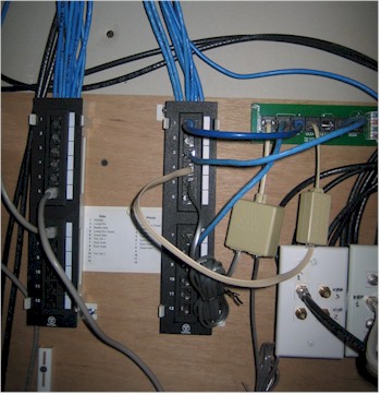
The photo of my entire current setup (Figure 14) isn’t that pretty to look at, but it gets the job done with room to spare in 2 ft. X 2 ft. of wall space. I ended up rearranging the coax panel boxes when I added the equipment shelf, which was no problem due to my releasable cable tie system (I just tucked the slack cable up between the floor joists).

Figure 14: The whole thing
(click image to enlarge)
This view also shows the two coaxes from my satellite dish coming in from the top left of the photo, crossing over, and connecting directly to the coax panel, which then patches it to the outlet box upstairs in the living room where a DirecTV Tivo is located. The other patch cable takes the RF output from the Tivo over to the TV in my wife’s studio. I set her up with a Terk Leapfrog LF-IRX Remote Control Extender that allows her to command the “family” PVR. Relatively low-tech, yes, but free of DRM and streaming hassles.
I also added an inexpensive floor-standing shelf next to the panel, which holds the APC UPS, usually an Infrant NAS, and an assortment of products waiting test or to be returned to their manufacturers. I decided against putting in a 19 inch rack because, as you can see, my equipment doesn’t require one, they’re a relatively expensive way to hold things and I had plenty of other ways to spend that money in a new home!
I’m pretty happy with how things turned out and think that paying to have the cabling run, but doing the termination yourself is a great way to put some “sweat equity” into a home networking installation without having to pay too much sweat!
But enough about me, how about you? If you’d like to share your story on how you approached the installation of a whole-house network, just drop me a line. A few pix and a short description of what went well, what didn’t and lessons learned are all that I need to create a short article that others can benefit from. You know you want to, sooo…just do it now!