Introduction
Updated 20 Oct 2010: Clarify test setup
For wireless products tested after July 24, 2011, see this article.
For wireless products tested between March 2007 and June 19, 2008, see this article.
For wireless products tested after November 2005 to before March 2007, see this article.
For wireless products tested after October 1, 2003 to before November 2005, see this article.
For wireless products tested before October 1, 2003, see this article.
With the loss of the Azimuth system, SmallNetBuilder has returned to using open-air testing in a residential environment to test wireless product performance. The method is essentially the same used in our previous open-air method, but with a sixth location added and the locations renamed.
The reason for the sixth test location was prompted by looking over past test data, including the study done for the Converting Path Loss to Distance How To. We found that test Locations 2 and 3 tended to produce similar results. Similarly, Locations 4 and 5 also produced similar results, including the fact that many products were not able to maintain a connection with either location.
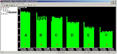
Figure 1 shows a NetStumbler signal plot of the six new test locations, which are called A through F. The old test location numbers (1-5) are also shown in red, so that you can relate the two. The new Location D has a signal level roughly 10 dB lower than Locations B and C and about 10 dB higher than Locations E and F.
Figure 1: Netstumbler signal plot of New and Old Test locations
Testing has shown that Location D will be helpful in showing product performance that is in the "waterfall" portion (where throughput starts to fall off) of a throughput vs. signal level curve. Note that the test locations are arranged in declining signal level order. Note also that the new test locations still cannot be used to directly relate throughput to distance, since every wireless environment is different.
Figure 2 shows an example of how data will be presented for comparison. This stacked column chart shows a comparison of throughput at each test location for a single dual-band product in each of its bands and channel widths. Similar plots will be produced that compare multiple products at each test location for a given test mode.
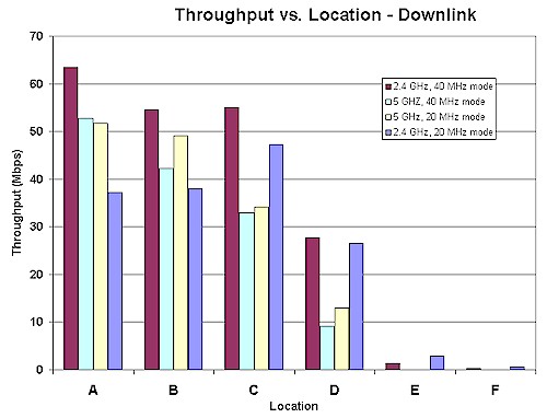
Figure 2: Sample Throughput vs. Location plot
Environment
The Test Environment is an approximately 3300 square foot two-level home built on a hillside lot with 2×6 wood-frame exterior walls, 2×4 wood-frame sheetrock interior walls, and metal and metalized plastic ducting for the heating and air conditioning system. The Access Point (AP) or wireless router is placed on a four foot high non-metallic shelf away from metal cabinets and RF sources.
Figure 3 shows a simplified layout of the lower level and two of the five test locations.
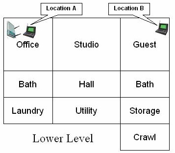
Figure 3: Lower Level Test Locations
Note that the Laundry, Utility, Storage and Crawl(space) areas are below grade, but the rest of the rooms on the lower level have daylight access. Figure 4 shows the upper level layout and the other four test locations.
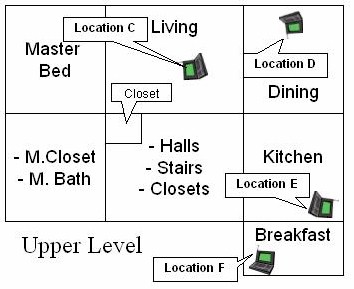
Figure 4: Upper Level Test Locations
The lower-level corner office is not the best location for placing a wireless router or access point for whole-house coverage, but serves the purpose well for pushing products to their limits. Note that the orientations of the icons for the AP and notebooks in Figures 3 and 4 are significant and indicate actual orientation of the test notebook.
The notebook carrying the client adapter under test is oriented as a user would naturally do in each location. Client adapters are plugged into USB or Cardbus slots on the left side of the notebook.
Here are descriptions of the six test locations:
- Location A: AP and wireless client in same room, approximately 6 feet apart.
- Location B: Client in room on same level, approximately 45 feet away from AP. Two sheetrock walls between AP and Client.
- Location C: Client in upper level, approximately 25 feet away (direct path) from AP. One wood floor, sheetrock ceiling, no walls between AP and Client.
- Location D: Client in upper level, approximately 35 feet away (direct path) from AP. One wood floor, one lower level sheetrock wall, sheetrock ceiling between AP and Client.
- Location E: Client on upper level, approximately 55 feet away (direct path) from AP. Two to three interior walls, one wood floor, one sheetrock ceiling and stainless-steel refrigerator between AP and Client.
- Location F: Client on upper level, approximately 65 feet away (direct path) from AP. Four to five interior walls, one wood floor, one sheetrock ceiling between AP and Client.
While you might think that Location F is the most difficult, Location E is usually the toughest. This is probably due to the combination of antenna orientation, stainless-steel clad appliances close by, and the desktop test location being sunk about 6 inches below an adjoining quartz-composite countertop.
Test Description
Updated 20 Oct 2010: Clarify test setup
Ixia’s IxChariot network peformance evaluation program is used with the test configuration shown in Figure 5 to run tests in each of the test locations. Testing is done using the SNB standard wireless test client, an Intel Wi-Fi Link 5300 AGN mini-PCIe card in a Dell Mini 12 running WinXP Home SP3.
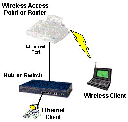
Figure 5: Wireless test setup
All routers / APs are generally reset to factory defaults. On wireless routers, all testing is done on the LAN side of the router so that the product’s routing performance does not affect wireless performance results, i.e. the Ethernet client is connected to a router LAN port.
At each test location, the IxChariot Throughput.scr script (which is an adaptation of the Filesndl.scr long file send script) is run for 1 minute in real-time mode using TCP/IP in both uplink (client to AP) and downlink (AP to client) directions. The only modification made to the IxChariot script is typically to change the file size from its default of 100,000 Bytes to 300,000 Bytes of data for each file send for 802.11g products and to 1,000,000 Bytes for draft 802.11n products.

